
Basic Documentation
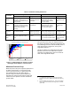
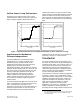
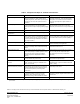
Table Of Contents

Product or company names mentioned herein may be the trademarks of their respective owners. © 2009 Siemens Industry, Inc.
Siemens Industry, Inc. Printed in the USA
Building Technologies Division Document No. 149-985
1000 Deerfield Parkway Page 8 of 8
Buffalo Grove, IL 60089-4513
USA
Table 2. Comparison of Major Air Terminal Characteristics.
Attribute Venturi Air Valve Single-Blade Damper
Physical Configuration More complex physical configuration with more
operating components. Higher airflows require
multiple ganged units, which takes up more space,
increases the unit cost, and requires more duct
transitions.
Very simple physical configuration with minimal
operating components – only two damper shaft
pivot points. Duct transitions and the installation
are easier especially when higher airflows are
required.
Airflow Capacity Lower maximum airflow due to less airflow area for
a given size (diameter) of air terminal. Higher
airflow capacities require multiple (parallel ganged)
units.
Higher maximum airflow (70% to 100% greater
than the Venturi air valve) for the same size
(diameter) air terminal due to the large airflow area.
Cost Higher cost per unit. Lower cost per unit.
Mechanical Pressure
Independence
Yes (within a specific static pressure range) No
Control Curve Non-Linear (equal percentage) airflow control
action. (Linear control is accomplished by applying
a controller with closed loop control capability or
the unit must be factory calibrated for use with an
open loop controller.)
Non-linear (quick opening) airflow control action.
(Linear control output is accomplished by applying
a controller with closed loop control capability.)
Control Accuracy Nominally +/- 5% as an open loop device Depends on the airflow sensor; which should be
selected according to the application
Control Turndown 8-to-1 with closed loop control.
From 10-to-1 through 16-to-1 without closed loop
control.
Limited by leakage around damper seal.
Sometimes reaches 20-to-1.
Minimum Pressure Drop 0.30 in. WC (75 Pa) for low pressure model.
0.60 in. WC (750 Pa) for medium pressure model.
(This pressure drop is required to enable the
mechanical pressure independent function to
operate.)
Pressure drop is very low (0.01 to 0.05 in. WC or
2.5 to 12.5 Pa) with the damper wide open.
(No minimum pressure drop is required for
operation.)
Sound Generation Somewhat higher than a round blade damper for
the same airflow and pressure drop.
Somewhat lower than a Venturi air valve for the
same airflow and pressure drop.
Materials available to resist
corrosion
Spun aluminum outer shell with Hersite
®
and
Teflon
®
protective coatings are available for the
shell, cone and shaft.
Multiple materials available for the entire unit:
Galvanized steel, Type 316L Stainless Steel and
Teflon
®
coating.
Susceptibility to the effects of
chemical or airborne particulate
Particulate accumulation on the internal surfaces
will degrade the self-contained (non-closed loop)
pressure independent function. External closed
loop control is required to prevent degraded
performance.
Particulate accumulation will not degrade the
closed loop control action.
Installation Requirements Each unit must be installed in either the horizontal
or vertical orientation in which it was factory
calibrated. Higher airflow (ganged) units are
cumbersome, heavy, and more difficult to install.
Units can be installed in any orientation—vertical,
horizontal, or angular. Higher airflow units are less
cumbersome.
Maintenance No routine maintenance required.* No routine maintenance required.*
* All laboratory ventilation safety standards require periodic (typically on an annual basis) inspections of a laboratory ventilation system's
performance.