
Installation Instructions

Installation Instructions
Document No. 540-209
Rev. 3, March, 2001
Room Pressurization Controller –
Electronic Output
Page 1 of 8
Product Description
These instructions explain how to field install or
replace a Room Pressurization Controller (RPC) –
Electronic Output with or without Autozero Modules.
Product Number
540-516 Room Pressurization Controller –
Electronic Output
540-517 Room Pressurization Controller –
Electronic Output with Autozero
Modules
Shipping carton includes a controller assembly
(controller board and cover), a mounting rail, Autozero
Modules with brackets (optional), and two self-
tapping/drilling screws.
NOTE:
Keep the controller assembly in its static-proof
bag until installation.
Installation Conventions
CAUTION:
Equipment damage or loss of
data may occur if the user
does not follow procedure as
specified.
Required Tools
x
Electro-Static Discharge (ESD) wrist strap
x
Small flat-blade screwdriver
x
Medium flat-blade screwdriver
x
Medium-duty electric drill
x
1/4-inch (6.35 mm) hex nut bit
x
Portable Operator’s Terminal with Controller
Interface Software (CIS) Rev. 2.0 or higher
(controller replacement only)
Additional tools needed if not using self-tapping
option:
x
1/4-inch (6.35 mm) hex nut driver
x
1/8-inch (3 mm) bit
Prerequisites
x
Room temperature sensor installed (optional)
x
Air velocity sensors installed in ducts
x
24 Vac Class 2 power source
x
Supply power to the unit is OFF
x
Autozero Modules with brackets are on hand
(optional)
x
If required, controller enclosure installed
Expected Installation Time
New controller installation 10 min.
Replacement with removable terminal
blocks
6 min.
Replacement without removable
terminal blocks
16 min.
NOTE:
You may require additional time for database
work at the field panel.
New Installation Instructions
NOTE:
For Autozero Module installation, refer to
Installation Instructions
(540-199).
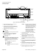
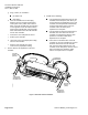
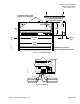
1. Using the mounting rail as a template (See
Figures
1
and
2
), mark the location for the two screw holes
where you will install the controller assembly.
2. Do
one
of the following:
x
If using the self-tapping screws:
Using the
drill and the hex nut bit, fasten the mounting
rail. (Screws do not require starter holes.)
x
If not
using the self-tapping screws:
Drill
two 1/8-inch (3 mm) pilot holes. Align the
mounting rail with the holes. Using the hex nut
driver, fasten the mounting rail with the No. 6
or No. 8 screws.