
Installation Instructions

Document Number 540-209
Installation Instructions
Rev. 3, March, 2001
Page 2 of 8
Siemens Building Technologies, Inc.
24 V-AC
FLN
TRUNK
COVER
BST
CH
+-
SRXTX RTS
DO 1 DO 2 DO 3 DO 4 DO 5 DO 6
NO C NO C NO C NO C NO C NO C
DO 7
NO C
DO 8
NO C
DI 3 DI 2
AI 3
1 2 3 4 5 6 7 8 9 10 11 12 13 14 15 16 17 18 19 20
1 2 3 4 5 6 7 8 9 10 11 12 13 14 15 16 17 18 19 20
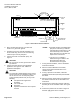
AIR VELOCITY
SENSOR PORTS
HI
LO
CONTROLLER
BOARD
POWER
TRUNK
TERMINATIONS
TRANSMIT LED
RECEIVE LED
BST LED
FLN
TRUNK
TERMINATIONS
INPUT / OUTPUT TERMINATIONS
DO LEDS
MOUNTING
HOLE
(2)
MOUNTING
RAIL
ROOM TEMPERATURE
SENSOR / MMI PORT
TEC0044R5
LO
HI
CH
+-
S
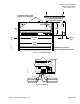
Figure 1. RPC without Autozero Modules.
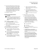
3. Place the ESD wrist strap on your wrist and
attach it to a good earth ground.
4. Carefully remove the controller assembly from
the anti-static bag. Center it over the mounting
rail and snap it securely into place.
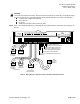
5. Connect the Floor Level Nework (FLN), see
Figure 4
.
CAUTION:
Do not connect an earth ground to the Shield
(S) terminal.
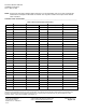
6. Connect the point wiring for the appropriate
application. See
Figure 6
. See
Table 1
for
application descriptions.
CAUTION:
The Controller’s Digital Outputs (DOs) control
24 Vac loads only. The maximum rating is 12
VA for each DO. Use an interposing 220V
4-relay module (P/N 540-147) for any of the
following:
x
VA requirements higher than
maximum.
x
110 or 220 Vac.
x
DC power.
x
Separate transformers used to power
the load.
NOTES:
1.Each DO provides a Normally Open
(NO) and a Common (C) terminal.
Terminate both connections of a 24
Vac load directly to the controller
board. Actuators use two DOs and
require three connections.
2. The 24 Vac “H” terminal is
switched through a TRIAC to the
NO terminations when the
associated DO is energized.
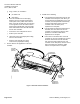
7. If using Autozero Modules, use the installation
instructions included.
8. After the Autozero Modules are installed,
connect the Autozero Module wires to the
controller at DO7.
9. If using a pressure mode switch, follow the
Installation Instructions
(540-719) included with
the switch.
10. After the pressure mode switch is installed, wire
the switch to DO8 and AI3 as described in the
instructions.
11. Plug the Room Temperature Sensor cable into
the RTS port on the controller board. See
Figure
1
.
12. Connect the power trunk as shown in
Figure 5
.
DO NOT apply power to the controller.