
Installation Instructions

Document Number 540-209
Installation Instructions
Rev. 3, March, 2001
Siemens Building Technologies, Inc.
Page 3 of 8
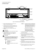
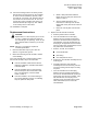
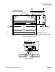
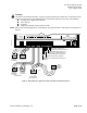
13. Connect the tubing from the air velocity sensor
pickups to the HI and LO ports on the controller,
or on the Autozero Modules (if present). Make
sure that the “HI” and the “LO” pressure sides of
the sensors are connected to the “HI” and “LO”
sensor ports on the controller (See
Figure 1
) or
Autozero Modules (See
Figure 2
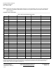
). See
Table 2
for air velocity sensor connections.
The installation is complete.
Replacement Instructions
CAUTION:
Replacement of a TEC requires you to record,
re-enter, or update the initial point values of
the controller you are replacing. These are the
points marked with an asterisk (*) on the CIS
display.
NOTE:
CIS Rev. 2.0 or higher is required for
controller replacement.
1. Place the ESD wrist strap on your wrist and
attach it to a good earth ground.
2. Before disconnecting the old controller, do
one
of the following:
If the new controller has a newer firmware revision
than the old controller, skip to the third bullet.
x
If the old controller communicates with the
field panel, update the controller initial values
at the field panel.
x
If the old controller does not communicate
with the field panel, but communicates with
CIS, or is stand-alone, record the initial
values in Table 3.
x
If the old controller is not communicating or
has a newer firmware revision, use following
steps to update the field panel:
a. Obtain a field panel Point Definition
Report for the LCTLR point. Record the
values in Table 3.
b. View the initial value block. (This
information is valid only since the last
update was made). Record the values in
Table 3.
c. Delete the LCTLR point from the field
panel.
3. Replace the old controller as follows:
a. Remove power from the controller.
b. If the old controller has the RTS plug
between the FLN and point terminations,
disconnect the wires from the power trunk
terminal block. If the old controller has the
RTS plug on the opposite end of the board
from the power trunk terminal block, remove
the power trunk terminal block.
c. Remove, in order, the controller’s:
x
FLN terminal block
x
point wiring
x
room temperature sensor
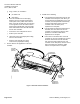
d. Remove the old controller assembly from the
mounting rail.
e. Carefully remove the new controller
assembly from the anti-static bag. Center it
over the mounting rail and snap it securely
into place.
f. If the old controller has the RTS plug
between the FLN and point terminations,
then remove all terminal blocks (except the
power trunk) from the new controller. If the
old controller has the RTS plug on the
opposite end of the board from the power
trunk terminal block, then remove all
terminal blocks.