
Installation Instructions

Document Number 540-209
Installation Instructions
Rev. 3, March, 2001
Page 4 of 8
Siemens Building Technologies, Inc.
g. Plug, in order, the controller’s:
x
pre-wired FLN
x
point wiring
h. If the old controller has the RTS plug
between the FLN and point terminations,
rewire power to the power trunk terminal
block. If the old controller has the RTS plug
on the opposite end of the board from the
power trunk terminal block, plug the power
trunk terminal block from the old controller
into the new controller.
i. Connect the room temperature sensor.
j. Power up the controller.
k. Label and remove the polyethylene tubing
from the old controller.
l. After the new controller is in place,
reconnect the polyethylene tubing.
4. Set the address and application at the new
controller.
5. Do
one
of the following:
x
If you updated the initial values from the old
controller at the field panel, then when you
set the address and application for the new
controller, the field panel will automatically
send the initial values down to the new
controller. Once this takes place,
replacement is complete.
x
If you manually recorded the initial values in
the table, then enter them into the new
controller. If a field panel is present, then
update the controller’s initial values.
Replacement is complete.
x
If there was no communication at the old
controller, or the new controller has a newer
firmware revision than the old controller,
then enter the initial values into the new
controller. At the field panel, add the LCTLR
point and update the controller’s initial
values. The replacement is complete.
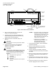
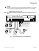
24 V-AC
FLN
TRUNK
BST
C
H
+-
S
RX
TX
RTS
D
O
1
D
O
2
D
O
3
D
O
4
D
O
5
D
O
6
N
O
C
N
O
C
N
O
C
N
O
C
N
O
C
N
O
C
D
O
7
N
O
C
D
O
8
N
O
C
D
I 3
D
I 2
A
I 3
1
2 3
4 5
6
7
8 9
10
1
1 12
13
1
4
1
5
1
6 17
1
8
1
9
2
0
1 2 3 4 5 6 7 8 9 10 11 12 13 14 15 16 17 18 19 20
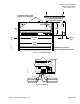
CONTROLLER
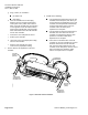
AIR VELOCITY
SENSOR PORTS
AIR VELOCITY
SENSOR PORTS
IN EXHAUST DUCT
TEC0214R5
AIR VELOCITY
SENSOR PORTS
IN SUPPLY DUCT
AUTOZERO
MODULE 1
(SUPPLY)
HI
HI
HI
HI
LO
LO
LO
LO
AUTOZERO
MODULE 2
(EXHAUST)
C H
+ - S
HI
LO
HI
TO TEC
TO AVS
LO
HI
LO
HI
TO TEC
TO
AVS
LO
Figure 2. RPC with Autozero Modules.