
Installation Instructions

Document Number 540-209
Installation Instructions
Rev. 3, March, 2001
Siemens Building Technologies, Inc.
Page 5 of 8
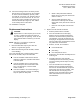
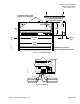
#8 TAPPING SCREW HOLE
11/64 (4) DIA. CLEARANCE
2-1/2 (64) CLEARANCE REQUIRED
FOR PROPER INSERTION OF
POLYETHYLENE TUBING
DIMENSIONS IN INCHES
MILLIMETERS IN PARENTHESES
4-1/8
(105)
10-29/32
(277)
3/16
(5)
TEC0050R4
C
L
11-9/32
(287)
1-27/32
(47)
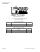
1 2 3 4 5 6 7 8 9 10 11 12 13 14 15 16 17 18 19 20
CH
+-
S
Figure 3. Mounting Dimensions.
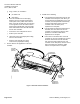
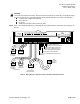
FLN
TRUNK
TX RX + - S BST RTS
(SHIELD) (SHIELD)
(+)
(+)
(-)
(-)
TEC0042R4
Figure 4. FLN Wiring.