
Installation Instructions

Document Number 540-209
Installation Instructions
Rev. 3, March, 2001
Siemens Building Technologies, Inc.
Page 7 of 8
CAUTION:
The Room Pressurization Controller – Electronic Output controls 24 Vac loads only. The maximum rating
is 12 VA for each DO. Use an interposing 220V 4-relay module (P/N 540-147) for any of the following:
x
VA requirements higher than maximum
x
110 or 220 Vac
x
DC power
x
Separate transformers used to power the load.
NOTE:
Refer to the unit wiring diagrams or consult with the local representative if terminations are missing or are
different.
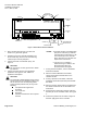
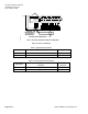
1 2 3 4 5 6 7 8 9 10 11 12 13 14 15 16 17 18 19 20
Y1 G
Y2
COM
CW
CCW
- OR -
(SUPPLY DUCT)
DAMPER
ACTUATOR
(P/N SQR81.1)
G = COMMON
DAMPER
ACTUATOR
(P/N 349-0100)
ROOM TEMPERATURE SENSOR
PRESSURE MODE SWITCH (OPTIONAL); OR,
SPARE AI (100K THERMISTOR ONLY); OR,
SPARE DI (DRY CONTACT CLOSURE ONLY)
WALL SWITCH (OPTIONAL); OR,
SPARE DI (DRY CONTACT CLOSURE ONLY)
ALARM OUTPUT (OPTIONAL); OR, SPARE DO
Y1 G
Y2
COM
CW
CCW
- OR -
(EXHAUST DUCT)
DAMPER
ACTUATOR
(P/N SQR81.1)
G = COMMON
DAMPER
ACTUATOR
(P/N 349-0100)
AVS 1 AND AVS 2 AUTOZERO MODULES (OPTIONAL); OR,
SPARE DO
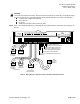
TECRPCEOWDR3
24 V-AC
TX
RX
FLN
TRUNK
+ - S BST
RTS
DO 1
NO C
DO 2
NO C
DO 3
NO C
DO 4
NO C
DO 5
NO C
DO 6
NO C
DI 3
AI 3
DI 2
DO 7
NO C
DO 8
NO C
1 2 3 4 5 6 7 8 9 10 11 12 13 14 15 16 17 18 19 20
C H
VALVE ACTUATOR
(EVA 339) (OPTIONAL)
VALVE
ACTUATOR
(P/N SQS8 ...)
(OPTIONAL)
Y2 G Y1
- OR -
O
P
E
N
CC
L
O
S
E
D
WHT
RED
BLK
+-
CH
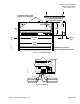
S
Figure 6. Wiring Diagram--Applications 2216 and 2218 with Hot Water Reheat.