
Data Sheet for Product

Page 2 of 5 Siemens Building Technologies, Inc.
• Set points and control parameters easily assigned
and changed using the Portable Operator’s
Terminal
• Electrically Erasable Programmable Read Only
Memory (EEPROM) used for storing set points
and control parameters—no battery backup or re-
entry of data required
• Quick return from power failure without operator
intervention
• Maintains room pressurization during transient
conditions, i.e., rapid hood sash movement
• Two controller options, both use the same air flow
measurement technology while offering options
for control of end devices
• Pneumatic Output – for control of pneumatic valve
and damper actuators
• Electronic Output – for control of 0-10V hot water
valves and the Laboratory Electronic Damper
Actuators
Laboratory Room Controller – Pneumatic
Actuation
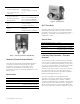
The Laboratory Room Controller-Pneumatic Actuation
consists of the Laboratory Control Module, two lab
pneumatic transducers for pressure control, one AO-P
Transducer for temperature control, two auto-zero
modules for airflow measurement accuracy and an
enclosure. All assemblies are pre-mounted and pre-
terminated (electric and pneumatic connections) within
the enclosure at the factory. External connections for
the pneumatic damper actuators and flow sensors are
located on the side of the enclosure. The LRC can be
factory mounted to the Laboratory Room Supply
Terminal or field mounted within the lab room.
The control algorithm is pre-programmed and
controllers are ready to operate after selecting the
application and assigning the controller’s address
using the Portable Operator’s Terminal. If desired, the
operator may use the Portable Operator’s Terminal to
adjust the air velocity set points in flow, differential
flow, room temperature set point and other set points.
Laboratory
LaboratoryLaboratory
Laboratory Controller Module
Controller Module Controller Module
Controller Module-
--
- Pneumatic
Pneumatic Pneumatic
Pneumatic
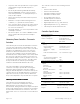
The Laboratory Controller Module includes a
microprocessor-based assembly with on-board
differential pressure transducers for airflow
measurement. Wiring termination for input and output
points, FLN communications, and power are provided
via removable terminal block connections. The room
temperature sensor is connected to an on board RJ-11
jack.
The controller connects to the following external
devices:
• Fume Hood Controller
• Fume Hood Flow Module
• Pneumatic Damper Actuators
• Pneumatic Hot Water Valve
• Room Temperature Sensor
• Portable Operators Terminal
• APOGEE Automation System
• Digital Input Devices (e.g., wall switches)
• Digital Output Devices (e.g., alarm horn)
• Laboratory Room Air Terminals boxes
Controller Specifications
Power Requirements
Operating Range
Power Consumption:
19 to 28 VAC 50 or 60 Hz
12 VA (Nominal) to
24 VA (Peak) @ 24 VAC
(plus loads)
Inputs
Analog
Room Temperature
Supply Airflow
Exhaust or 2
nd
supply
airflow
Fume Hood Exhaust Flow
Digital
Occupied Switch (optional)
Alarm Switch (optional)
1 temperature sensor
1 air velocity sensor
1 air velocity sensor
1 (0 –10) Vdc flow signal
1 DI
1 DI
Note: All Digital Input (DI) points are dry contact.
Outputs
Digital
Auto-zero
Pressure Alarm
(optional)
Room Occupied Status
(optional)
Supply Airflow Control
General Exhaust
Airflow Control
Spare
1 DO
1 DO
1 DO
2 DOs to pneumatic
2 DOs to pneumatic
1 DO
Note: All Digital Output (DO) points are 24 VAC optically isolated solid
state switches @ 0.5A.
Analog
Temperature Control
1 pneumatic output
Dimensions
Enclosure
Weight
13.5”W x 14.5”L x 4”D
(320 mm x 340 mm x 102 mm)
Approx. 10 lbs (4 kg)