
Data Sheet for Product

Siemens Building Technologies, Inc. Page 3 of 5
Control Performance
Controlled Temperature
Flow Control Speed of
Response
±
1.0
°
F (0.6
°
C)
Accuracy, Heating or Cooling
1.5 sec.
Environmental Conditions
Storage Temperature
Operating Temperature
Humidity Range
-40
°
F to 167
°
F (-40
°
C to 75
°
C)
32
°
F to 104
°
F (0
°
C to 40
°
C)
10 to 95% (non-condensing)
Agency Listings
FCC
UL
Class B, subpart J
916 PA ZX 864-UDTZ
Communications
Remote
Local
FLN Trunk
Portable Operator’s Terminal
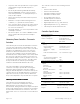
Figure 3. Laboratory Pneumatic Output Module.
Laboratory Pneumatic Output Module
The Laboratory Pneumatic Output Module (Figure 3)
contains the transducers that provide the signal
conversion from electronic to pneumatic. Two
modules are used within the Laboratory Room
Controller to interface to pneumatic dampers for room
airflow control.
Specifications
Maximum Input Pressure 30 psi
Air Consumption 38 SCIM (ml/sec)
Power Consumption 5 VA @ 24 VAC max.
Dimensions 2-1/2"W x 4-1/2"H x 1-1/4"D
(64 mm x 114 mm x 32 mm)
Weight 0.5 lb. (0.2 kg)
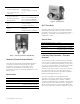
Figure 4. AO-P Transducer.
AO-P Transducer
The AO-P Transducer (Figure 4) contains the devices
that provide the signal conversion from electronic to
pneumatic. One transducer is used within the LRC to
interface to a pneumatic valve actuator for room
temperature control.
Specifications
Maximum Input Pressure 30 psi
Air Consumption 8 SCIM (ml/sec)
Power Consumption 1.0 VA @ 24 VAC max
Dimensions 7-1/4"W x 4-1/4"H x 3-1/16"D
(184 mm x 108 mm x 78 mm)
Weight 0.5 lb. (0.2 kg)
Laboratory Room Controller – Electronic
Actuation
The Laboratory Room Controller-Electronic Actuation
consists of the Laboratory Control Module, two auto-
zero modules for airflow measurement accuracy and
an enclosure. All assemblies are pre-mounted and pre-
terminated within the enclosure at the factory.
External connections for flow sensors are located on
the side of the enclosure. The LRC can be factory
mounted to the Laboratory Room Supply Terminal or
field mounted within the lab room.
The control algorithm is pre-programmed and
controllers are ready to operate after selecting the
application and assigning the controller’s address
using the Portable Operator’s Terminal. If desired, the
operator may use the Portable Operator’s Terminal to
adjust the air velocity set points in CFM, differential
flow, room temperature set point and other set points.