BACnet Programmable Fume Hood Controller 2-Position Constant Volume with Damper, Application 6740 Start-up Procedures Building Technologies 140-1342 2015-11-09 Restricted CPS
Table of Contents Before You Begin ............................................................................................................... 5 Verifying Power .................................................................................................................... 6 Verifying Slave Mode Application Number .......................................................................... 6 Setting Controller Address ....................................................................................
Configuring BACnet Parameters ....................................................................................... 18 Auto Discover and Auto Addressing .................................................................................. 19 Commissioning a Controller ............................................................................... 22 Flashing Controller Firmware ............................................................................................. 25 4 Siemens Industry, Inc.
Before You Begin Verifying Power Before You Begin WARNING A fume hood is a safety device. Anyone attempting to start up a Fume Hood Controller and its related equipment should have completed Operations Training. Generic Controller I/O Layout. See Wiring Diagram for application specific details. At the job site, locate the major control system and the mechanical and electrical drawings.
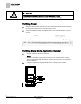
Before You Begin Verifying Power CAUTION A separate power supply is required if a 4-20 mA sensor is used. Failure to follow wiring precautions will result in equipment damage. Verifying Power 1. Verify that the controller has 24 Vac power and that the fuse has been inserted into the trunk or that power to the transformer is ON. 2. Verify that the Basic Sanity Test (BST) LED on the controller flashes once per second. Verifying Slave Mode Application Number 1. Plug the cable into the micro USB port.
Before You Begin Setting Controller Address Setting Controller Address 1. In WCIS, select View > Edit/View Reports. 2. Select a report from the list and click Apply. 3. Set CTLR ADDRESS to the BACnet MS/TP MAC address. (0 through 127 for Master; 128 through 254 for Slave). NOTE: See the WCIS Online Help for instructions on auto-addressing on the network. Otherwise, set the controller address and MS/TP network baud rate prior to connecting the controller to the network.
Before You Begin Setting Duct Area Setting Duct Area If provided, enter the duct area (sq ft or sq m) into DUCT AREA. If you do not know the duct area, use the appropriate tool to calculate it, or use one of the following equations to calculate it manually: Area = Round Duct Rectangular Duct Area in Sq. Ft. (Dimensions in inches) π x R2/144 (where R = radius of duct) Width x Height/144 Area in Sq.
Before You Begin Automatic Calibration Option 1. Set FLO COEF to initial values that match your hardware configuration. 2. Work with a balancer to obtain the exact value(s) for FLO COEF using the following formula to fine-tune the flow coefficient: New Flow Coefficient = (Actual Volume ÷ Controller Volume) × Old Flow Coefficient The actual volume is the value obtained from the balancer’s measurements. The controller volume is the value obtained from EXH VOL.
Before You Begin Setting Display Weight Setting Display Weight Set DISPLAY WT to a value of 0 through 100% (default is 100%). The suggested value is 30%. NOTE: If DISPLAY WT is set to 100%, the exhaust volume displayed at the ODP may fluctuate rapidly. This rapid fluctuation is due to the constant adjustments of the FHC. When DISPLAY WT is set to a value less than 100%, the exhaust volume displayed at the ODP is a weighted calculated value.
Before You Begin Setting ODP Display Setting ODP Display Set ODP DISPLAY to the desired value. Values are CFM or MODE. In CFM, the ODP displays the exhausted CFM. Use the table below to set the value. The default value is MODE. ODP Display Cfm Mode Flow Setpoint Actual display on the ODP HI Cfm Low Cfm HI Low Setting Hi and Low Warn Limits Skip this step unless there is a special requirement on the job; the default will be used. 1. Change report to STARTUP. 2.
Before You Begin Setting Emergency Setpoint Setting Emergency Setpoint Skip this step unless there is a special requirement on the job, the default will be used. Set EMER STPT to a value of 0 through 255%; default value is 150%. This percentage, multiplied by the normal EXH STPT, is used to set the fume hood to a safe operating level during the second phase of the emergency purge sequence.
Before You Begin (Optional) Calibrating the DP Transmitter without an Autozero Module Setting Transmitter Range 1. Set TRANS RANGE to the value printed on the differential pressure transmitter, typically: 0.1 in. WC (25.3 Pa), 0.25 in. WC (62.275 Pa), 0.5 in. WC (124.55 Pa), or 1.0 in. WC (249.1 Pa). Any value from 0.0 to 2.55 in. WC is acceptable. The default value is 0 in. WC. 2.
Before You Begin (Optional) Calibrating with an Autozero Module (Optional) Calibrating with an Autozero Module This section is for fume hoods with an external pressure sensor and an Autozero module. If the DP Transmitter is slightly out of adjustment, you can compensate for that within the controller. 1. Set REPORT to AIRFLOW IN. 2. Set CAL AIR to YES. When calibration is completed, this point will automatically change back to NO.
Before You Begin Setting AO2 Voltage Minimum NOTE: AO2 DEADBAND can be set from 0 to 102% in 0.4% increments. 0% will give the actual flow all the time. This signal may be too bouncy to give a stable output and will cause short-term room instability during fume hood sash movements. A 10% deadband is equal to ±5% of the flow. Any value over 100% will turn the feature off and revert to standard control. For stable pressure reading, lower the AO2 DEADBAND.
Before You Begin Loop Tuning Procedures General Information The FHC uses one Proportional, Integral, and Derivative (PID) loop. It is similar to the LOOP in a PPCL statement except gains are smaller by a factor of 1000. The process variable (PV) is EXH VOL. The setpoint is EXH STPT. The control variable (CV) is DMPR CMD. You can evaluate loop performance and do loop tuning by observing the display at the Operator’s Display Panel.
Before You Begin Loop Tuning Procedures Exhaust Flow Accuracy Verification This section presents the steps for verifying the exhaust flow accuracy. NOTE: It is recommended that this procedure be performed with the balancer so that the flow coefficient is coordinated with the measured exhaust flow. Verify the exhaust flow as follows: 1. Move the sash to an open position. Using a hand-held air velocity meter, perform a grid measurement of the face velocity.
Before You Begin Configuring BACnet Parameters Configuring BACnet Parameters Using WCIS, do the following: 1. From the Device menu, select Device Properties to configure BACnet parameters. 2. In the Object section, enter information for the following fields: – Instance Number – unique to BACnet network (valid values are 0 through 4,194,303). – Object Name – unique to BACnet network (30 alphanumeric character limit in RAD50).
Before You Begin Auto Discover and Auto Addressing Auto Discover and Auto Addressing An improved commissioning workflow has been designed for all BACnet PTEC controllers (standard 66xx applications) along with WCIS (Revision 4.0 and later). This provides the option to use the MS/TP network (using the field panel or a router) and the WCIS tool to discover and auto-address each controller. For more information, see the WCIS Online Help.
Before You Begin Auto Discover and Auto Addressing Configuration Settings Auto Address # Start - Beginning address number. An address is reserved for each discovered device starting with this number. Auto Instance # Start - Beginning instance number. An instance number is reserved for each discovered device starting with this number. Reassign Address and Instance drop-down menu - Reassigns the address and instance number of the selected device(s).
Before You Begin Auto Discover and Auto Addressing Configuring Discovered Devices Each device on the network must have unique identifiers in the following fields: Address Instance Object Name - 30 alphanumeric character limit for Siemens field panels. 1. To change any of these fields, click in that field and enter the desired value. 2. When all fields are defined, click Configure. All devices defined properly displays Addressed.
Before You Begin Auto Discover and Auto Addressing Commissioning a Controller Learning the Application Point Team Once a device has been addressed, select your application. Do one of the following: – Right-click in the Application column and select the desired Application. – Click Configure to load the device for your application. – Right-click on the controller and select Learn Point Team Descriptor. Import Data 1. Click the Import Pre-Engineered Data button.
Before You Begin Auto Discover and Auto Addressing You can configure values for multiple controllers with different applications by first selecting and making changes to one controller and then selecting all controllers and clicking Configure. NOTE: Once you select multiple controllers with different applications the Application tab goes blank. However, WCIS retains all changes and send the data for all selected controllers. .csv File Format The .
Before You Begin Auto Discover and Auto Addressing FIELDVAL This value must be set to the FIELDID. The format of this data is specific to the ID.
Before You Begin Flashing Controller Firmware Flashing Controller Firmware NOTE: When re-loading/flashing firmware, existing PPCL may no longer function correctly. FLT Procedure Use the Firmware Loading Tool (FLT) for this procedure. 1. Connect to the RTS port of the PTEC. 2. Set Communications to 38400 baud. 3. Click the Identify button. 4. Browse to the folder where the new firmware is saved. 5. Double-click the firmware file and then click Load. WCIS Procedure 1. Connect to the RTS port of the PTEC.
Issued by Siemens Industry, Inc. Building Technologies Division 1000 Deerfield Pkwy Buffalo Grove IL 60089 Tel. +1 847-215-1000 Document ID 140-1342 Edition 2015-11-09 © Siemens Industry, Inc., 2015 Technical specifications and availability subject to change without notice.