
Installation Instructions

Document No. 550-169
Installation Instructions
October 26, 2016
Page 2 of 9 Siemens Industry, Inc.
Product Numbers
Fume Hood Controller
Applications 2940, 2941, 2942
This controller requires Offboard
Air Module(s) (ordered and
shipped separately)
570-00700N
Offboard Air Module, order
separately
550-819B
Operator Display Panel II (ODP II)
575-820A
Power Module
AQM2200
Siemens fast-acting Lab Electronic
Actuator(s) – (order and ship
separately)
GNP191.1U
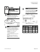
Shipping carton includes a controller assembly, a
mounting rail, and two self-tapping/drilling screws.
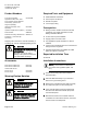
CAUTION
Keep the unit in its static-proof bag
until installation.
Otherwise, you run the risk of
damage to the printed circuit board
from electrostatic discharge.
Accessories
Room Sensor Cable 25 ft.
Room Sensor Cable 50 ft.
588-100A
588-100B
Vertical Sash Sensor
50 inch range
80 inch range
546-04000
546-04001
Warning/Caution Notation
WARNING
Personal injury/loss of life may
occur if you do not follow the
procedures as specified.
CAUTION
Equipment damage or loss of data
may occur if you do not follow the
procedures as specified.
Required Tools and Equipment
Small flat blade screwdriver
3/8-inch open end wrench
Needle nose pliers
1/4-inch poly tubing
Prerequisites
Wiring conforms to NEC and local codes and
regulations. For further information see the
Wiring Guidelines Manual
.
24 Vac Class II power available.
Supply power to the unit is OFF.
Any application specific hardware or devices
installed.
Fume Hood Controller Enclosure is mounted and
wiring has been roughed-in.
Operator Display Panel is installed and cable
pulled to location of controller.
Expected Installation Time
30 minutes
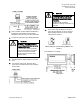
Installation Instructions
NOTE:
All wiring must conform to national and
local codes and regulations (NEC, CE,
etc.).
1. Secure the mounting rail in the controller’s
desired location.
2. Place the ESD wrist strap on your wrist and
attach it to a good earth ground.
3. Remove the controller from the static proof bag
and snap it into place on the mounting rail.
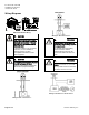
4. If the controller will be used with a field panel,
disconnect the field level network (FLN) trunk
from the field panel.
5. Wire the FLN trunk to the controller. After all
controllers are connected to the FLN, reconnect
the FLN trunk to the field panel.