
Installation Instructions
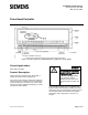

Document No. 550-169
Installation Instructions
October 26, 2016
Siemens Industry, Inc. Page 3 of 9
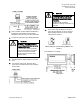
6. If the controller requires Offboard Air Modules,
install them now following the appropriate
Installation Instructions (see
Product Numbers
).
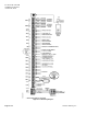
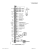
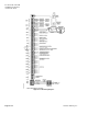
7. Connect the point wiring (see
Wiring Diagram
s).
CAUTION
DO Wiring – Each DO provides a
Normally Open (NO) terminal and a
Common (C) terminal.
To reduce noise and the potential
for ground loops, both connections
of a 24 Vac load must be wired
directly to the DO terminal on the
controller board.
8.
Plug the operator display cable into the ODP
port.
9.
Connect the power trunk. DO NOT apply
power to the controller without first consulting
the specialist.
CAUTION
It is important that the neutral that
supplies the TEC must be earth
grounded at the source of the 24
Vac power.
Possible erratic equipment
operation or damage if neutral is not
grounded.
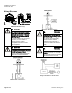
10.
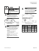
For a Fast Acting Lab Electronic Actuator,
verify that the switches are set as shown in
Figure
Switch Settings for the Fast Acting
Lab Electronic Actuator
.
Damper
Venturi Air Valve
Switch Settings for the Fast Acting Lab Electronic
Actuator.
The installation is complete.
Dimensions.