
Installation Instructions

Document No. 546-00333
Installation Instructions
December 8, 2011
Page 6 of 8 Siemens Industry, Inc.
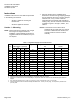
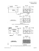
Figure 6. 18-inch Single Duct (High Capacity) Supply Terminal
with Reheat, Controls Enclosure, and LRC.
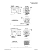
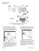
2. For angle iron hangers. Cut two pieces of
angle iron 4 inches wider than the terminal
(Figure 7) and mount the angle iron to the
bottom of the terminal using sheet metal screws.
Mount the angle iron so that it does not interfere
with internal parts or the access panel.
Figure 7. Angle Iron Installation.
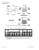
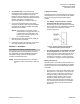
3. Drill holes in the angle iron to accommodate the
‘J’ bolts or threaded rod. If ‘J’ bolts are used,
secure them to the angle iron. Skip to Step 5 if
the terminal will be suspended using hanger
wire. Skip to Step 6 if the terminal will be
suspended using threaded rod.
4. For hanger brackets. Mount the four hanger
brackets to the top of the terminal using sheet
metal screws (Figure 8) so they do not interfere
with internal parts or the access panel.
Figure 8. Hanger Bracket Installation.
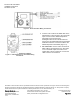
5. For hanger wire. Using hanger wire suspended
from the building’s bar joist or from mounting
anchors properly secured to the building’s
structure with lugs or poured-in-place hangers,
secure the unit and level it in each direction
(Figure 7 and Figure 8). Percussion nails are not
adequate anchors.