
Installation Instructions

Document No. 546-00333
Installation Instructions
December 8, 2011
Siemens Industry, Inc.
Page 7 of 8
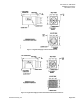
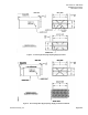
6. For threaded rod. Using threaded rod
suspended from the building’s bar joist or from
mounting anchors properly secured to the
building’s structure with lugs or poured-in-place
hangers, secure the terminal and level it in each
direction (See Figure 7 and Figure 8).
Percussion nails are not adequate anchors.
7. Connect the supply ductwork to the supply
terminal’s round inlet collar using the accepted
trade practice of welding or bolting the supply
terminal to the ductwork.
NOTE: The terminal’s round collar must be
positioned as the supply inlet. Also, if a
controls enclosure is attached to the
terminal, the controls enclosure must
be mounted vertically.
8. Seal all ductwork and check that the supply air
duct connections are airtight.
9. Connect the square slip and drive connection of
the supply terminal to the discharge duct.
Section 2 – Actuation
Field Panels and Unitary Controllers (UCs)
For application specific actuator wiring, reference
the appropriate controller installation instructions.
For actuator wiring, reference the appropriate
actuator Technical Instructions.
NOTE: For both field panels and UCs, the AO–P
Transducer used in these steps is P/N 545-
113.
Tubing Connections
Several pneumatic connections must be made from
the field panel or UC to the terminal box to operate
the AO-P Transducer and pneumatic damper
actuator.
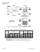
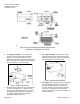
1. For damper, actuator and valve controls
mounted inside the controls enclosure.
Connect the 1/4-inch poly tubing from the 20 to
30 psi supply line to the port labeled “Supply Air
20 to 30 psi” on the side of the controls
enclosure (Figure 9).
Figure 9. Supply Terminal Pneumatic Piping
Connections and Terminal Knockout.
2. For reheat valve AO–P Transducers mounted
to the terminal box. For field panels and UCs,
connect the 1/4-inch poly tubing from the 20 to
30 psi supply line to the reheat valve’s AO–P
Transducer. Connect the 1/4-inch poly tubing
from the AO–P Transducer to the reheat valve.
Wiring Connections
Several electrical connections must be made from
the field panel or UC to the terminal box to operate
the AO-P Transducer and the differential pressure
transmitter.
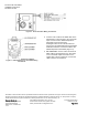
1. Connect a two-conductor 20 AWG cable to the
field panel’s 0 to 10V output or UC’s universal
output. Connect it to the AO–P Transducer or
through the wiring bushing/knockout on the
controls enclosure (Figure 9) to the AO–P
Transducer inside the enclosure. The wire
bushing can be removed and a standard 1/2-
inch conduit knockout fitting may be installed.
Connect the cable to the AO–P Transducer
(Figure 10).