
Installation Instructions

Document No. 546-00333
Installation Instructions
December 8, 2011
Information in this document is based on specifications believed correct at the time of publication. The right is reserved to make changes as
design improvements are introduced. APOGEE and Insight are registered trademarks of Siemens Industry, Inc. Other product or company
names mentioned herein may be the trademarks of their respective owners. © 2011 Siemens Industry, Inc.
Siemens Industry, Inc.
Building Technologies Division
1000 Deerfield Parkway
Buffalo Grove, IL 60089-4513
U.S.A
Your feedback is important to us. If you have
comments about this document, please send them
to SBT_technical.editor.us.sbt@siemens.com.
Document No.546-00333
Printed in the USA
Page 8 of 8
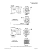
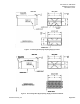
Figure 10. AO-P Transducer Wiring Connections.
Figure 11. Differential Pressure Transmitter Wiring
Connections.
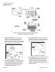
2. Connect a two-conductor 20 AWG cable to the
field panel’s 4 to 20 mA input or UC’s universal
input. Connect it to the differential pressure
transmitter or through the wiring
bushing/knockout on the controls enclosure
(Figure 9) to the differential pressure transmitter
inside the enclosure. Connect the cable to the
differential pressure transmitter (Figure 11).
3. For reheat coils. Connect a two-conductor 20
AWG cable to the field panel’s 0 to 10V output
or UC’s universal output and route it to the
reheat valve’s AO–P Transducer. Connect the
cable to the AO–P Transducer.
.