
Data Sheet for Product
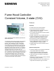
Table Of Contents

Siemens Industry, Inc.
Page 2 of 4
Applications
Operating independently, or integrated with the
APOGEE Automation System, the 2-state Constant
Volume Fume Hood Controller may be configured for:
• Display “HI” or “LO” setpoint status
• Display Exhaust Air Flow Rate
• Floating Output for high-speed or low-speed
electronic or pneumatic actuation of Dampers or
Venturi Air Valves
• Digital Output for HI/LO selection of 2-speed motor,
preprogrammed VFD or 2-position Venturi
Description
The VAV Fume Hood Controller consists of the
following components, which are required for each
fume hood:
• Fume Hood Controller
• Operator Display Panel and Cable
• Air Flow Measurement and Control Options
Controller
The Fume Hood Controller consists of a control circuit
board and metal enclosure. The enclosure may be
mounted directly on the exterior of the fume hood or
remotely on the laboratory wall or ceiling. The
controller circuit board is snap mounted inside the
enclosure and provides all wiring terminations for
input and output points, 24 Vac power, FLN trunk,
and the Operator Display Panel. A spare digital input
and output are provided for user applications such as
auxiliary sensors and alarms.
The control algorithms are pre-programmed. The
Fume Hood Controller is ready to begin operation
after selecting the proper application number defining
the network address, and appropriate set point and
control parameters using the laptop terminal. User
definable parameters include:
• HI and LO flow setpoints
• Alarm and Warning Limits
• Control PID Gains
• Display Resolution
• Alarm Delay
• Emergency Setpoint
The fume hood controller measures exhaust flow and
repositions actuation as necessary up to 10 times per
second to ensure maximum speed of response to
exhaust flow upsets. Concurrently, the controller
continually monitors and updates all fume hood
points including:
• High/Low Alarms
• Actual Exhaust Air Flow
• Setpoint Selected
Controller Specifications
Power Requirements
Operating Range
Power Consumption
18-30 Vac, 50/60 Hz
4.0 VA (nominal) @ 24 Vac
plus actuator loads
Inputs
Analog
Digital
1 Velocity Pressure Sensor (4-
20 mA)
1 Spare (0-10Vdc)
1 dry contact
Outputs
Analog
(0-10vdc)
Digital
(24 VAC optically
isolated solid state
switches @ 0.5A)
1 Exhaust Airflow Signal
1 Spare
1 Floating Actuator (2 DOs)
1 Spare
Package
Dimensions
Weight
6.5" H x 10.5" W x 3.0" D
(165 mm x 267 mm x 67 mm)
Approx. 3 lb. (1.35 kg)
Environmental
Storage
Temperature
Operating
Temperature
Operating Humidity
-40°F to 167°F (-40°F to 75°C)
32°F to 122°F (0°C to 50°C)
20% to 80% RH
non-condensing
Agency Listings
UL 916, PAZX & CSA Certified
FCC, Class B, Subpart J
CE, C-tick
Communications
Local Area Network
(FLN trunk)
Portable Operator’s
Terminal
RS-485 4800 baud
RS-232 1200 baud
Control Performance
Speed of Response
<1 second to flow change
Air Flow Measurement
Range
Accuracy*
0 – 2.5" wc
±3.0%
*Accuracy is shown in percent of Actual Airflow and includes differential
pressure transmitter accuracy.