
Installation Instructions

Document No. 546-00330
Installation Instructions
December 8, 2011
Siemens Industry, Inc.
Page 3 of 6
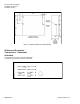
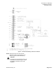
Airflow Connections – Electronic
Actuation
Using Figure 3 as a guide, make the appropriate
connections to the ports on the side of the LRC.
Figure 3. Airflow Connections for Electronic Actuation.
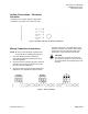
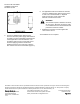
Wiring Connection Instructions
NOTE: Be sure to follow all safety regulations and
local codes when installing this equipment.
1. If the LRC will be used with a field panel,
disconnect the field level network (FLN) trunk
from the field panel.
2. Connect the FLN trunk wiring (Figure 4). After all
controllers are connected to the FLN reconnect
the FLN trunk to the field panel.
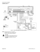
3. Connect the point wiring for the appropriate LRC
applications. For applications using pneumatic
actuators, see Figure 5. For applications using
electronic actuators, see Figure 6. Wires shown
in black must be connected in the field, while
those shown in gray are wired in the factory.
CAUTION:
The LRC DOs control 24 Vac loads only.
The maximum rating is 12 VA for each DO.
For higher ratings an interposing relay must
be used.
Figure 4. FLN Trunk Wiring.