
Installation Instructions

Document No. 546-00330
Installation Instructions
December 8, 2011
Information in this document is based on specifications believed correct at the time of publication. The right is reserved to make changes as
design improvements are introduced. APOGEE and Insight are registered trademarks of Siemens Industry, Inc. Other product or company
names mentioned herein may be the trademarks of their respective owners. © 2011 Siemens Industry, Inc.
Siemens Industry, Inc.
Building Technologies Division
1000 Deerfield Parkway
Buffalo Grove, IL 60089-4513
U.S.A
Your feedback is important to us. If you have
comments about this document, please send them
to SBT_technical.editor.us.sbt@siemens.com.
Document No.546-00330
Printed in the USA
Page 6 of 6
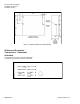
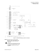
Figure 7. Terminal Block.
5. Connect a certified 24 Vac Class II power
source to the LRCs power supply terminal block
by inserting a 1/8-inch flat-blade screwdriver into
a rectangular slot on the terminal block. The
screwdriver will come into contact with a lever.
Continue applying pressure until the lever
releases and moves out of the way. Insert the
wire and then remove the screwdriver (Figure 7).
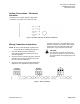
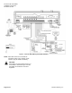
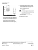
6. For applications that use the electronic actuator,
connect a certified 24 Vac Class II power source
to each unit on terminal block J1. Separate
power sources may not be used for the
electronic actuator and the LRC.
WARNING:
This actuator requires a maximum of 20 VA,
24 Vac source. DO NOT connect any other
non-isolated devices to the transformer that
powers the electronic actuator.
7. Replace the enclosure cover and tighten the
cover screws 1/4 turn.
The installation is now complete.