
Installation Instructions
Document No. 546-00321
Installation Instructions
Rev. 3, February, 2000
Page 2 of 7 Siemens Building Technologies, Inc.
Instructions
The FHM Hood Evaluation Kit Installation
Instructions are presented in eight sections:
1. Finding The Ideal Location for a Mobile Sample
Tube or an Averaging Tube
2. Assembling the Mobile Sample Tube and
Monitor Set Up
3. Mobile Sample Tube Starting Location
4. Evaluating Single Vertical Sash Configuration
5. Evaluating Horizontal Sash Configuration
6. Evaluating Combination Sash Configuration
7. Creating a Permanent Sample Tube for Vertical
Sash Fume Hoods
8. Creating a Permanent Sample Tube for
Horizontal or Combination Sash Fume Hoods
Section 1: Finding the Ideal Location for
a Mobile Sample Tube or an Averaging
Tube.
NOTE:
These instructions stress that the CAL
RAW (Point 88) reading is essential to
calibrating a fume hood. CAL RAW is the
raw airflow reading from the sensor within
the FHM. As the airflow through the FHM
increases the value of CAL RAW
increases. Once the CAL RAW readings
meet the four criteria listed below, the FHM
should be easy to calibrate.
1. The FHM will calibrate more efficiently the more
the value of CAL RAW varies as the face area
changes. Minimum values around the 60 to 70
range and maximum values of at least 120 or
greater will be easier to calibrate than CAL RAW
numbers with a smaller span.
2. A fume hood that has multiple vertical sashes or
horizontal sashes requires CAL RAW to give
repeatable readings in all sash positions. A fume
hood with several vertical sashes and a single
point sensing in the right sidewall may give a
greater change in CAL RAW values when the
right sash is moved compared to the left sash.
This situation is the same for fume hoods with
multiple horizontal sashes or combination hoods
with both types of sashes. It may be necessary
to construct a mobile sample tube to efficiently
obtain repeatable readings.
3. The values of MIN RAW (Point 75) and MAX
RAW (Point 71) should not approach the end
points of the FHM sensor range. The NO FLOW
condition occurs when a piece of tape is placed
over the sidewall adapter on the inside of the
hood. This NO FLOW value will be
approximately 50 raw counts; therefore, the
minimum MIN raw value should be at least 60
raw counts. The sensor upper limit is 255 raw
counts; therefore, the maximum MAX raw value
should be no more than 245 raw counts.
4. When the characteristics of the hood do not
allow the CAL RAW range to be as wide as
stated in Criteria 1, then the MIN, MID, and MAX
RAW numbers should be evenly spaced. If the
range of numbers are 57 to 83 and the NO
FLOW reading is 55, then the MIN, MID, and
MAX RAW numbers should be about 60, 70,
and 80, not 60, 65, and 80.
Section 2. Assembling the Mobile
Sample Tube and Monitor Set Up.
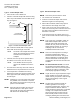
1. Place one end of the flexible tube to the back of
the FHM and place the other end into the
straight end of the PVC tubing.
2. Supply power to the FHM with the portable
transformer. Use Voyager to perform the
following steps:
a. Set the application to 651 and change
reports to the Factory Cal Report.
b. Set the DISPLAY WT (Point 95) to 40% and
set DISPLAY RES (Point 92) to 3.
c. Reset the MIN, MID, MAX FVEL,andRAW
values to the factory defaults.
NOTE:
With the FVEL and RAW values equal (the
factory default values) for each of the 3
calibration points, the FHM will display the
RAW values from the sensor. This will
allow you to use the display when looking
for RAW values in the following
procedures.
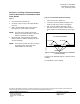
Section 3. Starting Location for the
Mobile Sample Tube.
NOTE:
For the following procedures, the mobile
sample tube should have the holes in the
side covered with masking tape and the
hole in the end open to simulate the
standard sidewall adapter.