
Installation Instructions
Document No. 546-00321
Installation Instructions
Rev. 3, February, 2000
Page 4 of 7 Siemens Building Technologies, Inc.
B. The raw signal bounces too much to
calibrate.
NOTE: This condition is caused by turbulent
airflow in the hood or by the airflow in
the room.
i. If the turbulent air is caused by poor room
conditions, then use the smoke tubes or some
other safe means to visualizehowtheair
currents move around the room. If there are
strong currents moving across the sensor
opening then move the FHM or change the
flow patterns in the room by diverting diffusers.
ii. If the turbulent air is caused by conditions
within the fume hood, move the sample tube
to a completely different location in the hood.
Look for the location using smoke tubes or
some other safe means where the air currents
do not appear to be as turbulent. See Step 1
at the beginning of this section and retest the
FHM.
iii. Proceed to Step 6 to take an averaging
reading.
C. The signal increases drastically when
the bypass is exposed.
i. The bypass area and not the overall face area
are controlling the sample point. If the fume
hood is equipped with fan powered auxiliary
bypass air then air may be forced across the
sensor giving inaccurate readings. The sample
point must be lowered or an averaging tube
should be installed. To lower the sample point,
reposition the sample tube and refer to the
beginning of this section and test the FHM.
ii. Proceed to Step 6 to take an averaging
reading.
6. If it has been determined that a Single Point
Mobile Sample Tube is not achieving accurate
readings, then an Averaging Sample Tube may
be required to make the FHM work.
7. Remove the Mobile Sample Tube from the fume
hood.
8. Take the Mobile Sample Tube and cover the
hole on the end and uncover the holes down the
length of the tube.
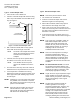
9. With the holes facing the rear of the fume hood
and the tube parallel to the sashes, place the
tube vertically with the top 3 inches above the
highest sash opening and 6 to 8 inches back
fromthesashtrack.
10. Move the sashes up and down to determine if
the FHM displays an acceptable reading. If the
readings are still not acceptable, then move the
averaging tube up and down, forward and back.
11. Retest the FHM until the conditions improve.
12. If a sampling tube solves the problem, then
proceed to
Section 7. Creating a Permanent
Sample Tube for Vertical Sash Fume Hoods,
and construct a permanent sample tube.
Section 5. Evaluation of Horizontal Sash
Configuration.
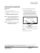
1. Move all the sashes to the left and then to the
right. As the sashes move, watch the display to
determine if the tube location reacts similarly to
open area on both the left and right sides.
2. If the FHM responds in an acceptable manner,
then mark the location of the tube where the
sidewall adapter will be installed. If
unsatisfactory results are obtained, then
continue with Step 4.
3. Move the sample tube to a completely different
location in the hood. Look for the location using
smoke tubes or some other safe means where
the air currents do not appear to be as turbulent.
See Step 1 at the beginning of this section and
retest the FHM.
4. Retest the FHM until the conditions improve. If
satisfactory results are still unobtainable, then
continue with Step 6.
5. As the horizontal sashes are moved, the signal
is stronger on the side of the FHM and weaker
on the opposite side of the FHM. See
Section 8.
Creating a Sample Tube for Horizontal
or
Combination Sash Fume Hoods
to solve this
condition.