
Installation Instructions

Document No. 546-00321
Installation Instructions
Rev. 3, February, 2000
Page 6 of 7 Siemens Building Technologies, Inc.
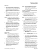
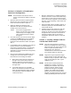
Type 1. Vertical Sample Tube.
1. Use 1/2-inCH. PVC schedule 40.
2. Construct a vertical sample tube 24 inches long
with a cap on the bottom and a 90°elbow on the
top. See Figure 1.
SASH
ELBOW
24" SAMPLE TUBE
HOLES FACETHE REAR
HOOD
WALL
1-1/2"
LEAVE TOP 4" BLANK
FUM0245R1
Figure 1. 24 inch Vertical Sample Tube.
3. With a 1/8-inCHdrillbit; drill 9 evenly spaced
holes down the entire length of the tube.
NOTE: The holes in the sample tube should
always face towards the back of the
hood when the installation is
complete.
4. If desired, the end cap can be replaced with a
90° elbow, 1 inch of PVC, and an end cap.
NOTE: This will allow the end cap to be
glued to the sidewall to secure the
tube.
5. The holes in the tube may need to be raised or
lowered based on the performance in the hood.
6. If the sample tube is installed and a strong
bypass flow controls the signal, then block 1 to 3
of the upper holes (with masking tape) and test
the tube again.
NOTE:
If blocking 1 to 3 of the upper holes solves
the problem, then reconstruct a new tube
with 9 holes evenly spaced, leaving the top
portion of the tube blank.
NOTE:
When the tube is installed, the top of the
tube should have a short piece of PVC
tube through the fume hood wall where it
will attach to the flexible tubing.
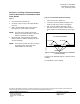
Type 2. Horizontal Sample Tube.
NOTE:
This tube is placed under the airfoil.
1. Use 1/2 inch PVC schedule 40.
2. Construct a horizontal sample tube at least
2/3rds the length of the sash opening.
3. With a 1/8 inch drill bit; drill 9 evenly spaced
holes down the entire length of the tube.
4. Place a cap on one end and a coupler on the
other end. These two pieces raise the tube off of
the work surface and allow air to flow around
both sides of the tube.
5. In the opened end of the coupler, place a 1 in.
piece of 1/2 inch PVC tube and insert a length of
tube.
NOTE:
Type 1 and Type 2 Sampling Tubes are
both efficient sample tubes. Their use
depends upon hood construction and
whether the user prefers the tube to be
visibly detected. Section 8. Creating a
Sampling Tube for Horizontal or
Combination Sash Fume Hoods.
NOTE:
There are several options in creating a
permanent sampling tube inside a
horizontal sash fume hood. The type of
tube that will work on a particular hood
must be determined on site taking into
consideration all fume hood and lab room
variables.
NOTE:
For horizontal fume hoods.
If the hood
has permanent perforated bypass, then
attach the tube to the center of the bypass
and move the sashes to determine if the
FHM displays appropriate readings.
NOTE:
Larger sizePVC may be required for larger
hoods. Smaller sizePVC will restrict the
airflow and may not provide a wide enough
range of raw readings to offer a good
calibration curve.
NOTE:
The directions mentioned below are
sufficient guidelines for creating a
permanent sampling tube, however, they
may be modified to work on different
hoods provided the FHM gives acceptable
readings. The sample tube should be
placed at least 1/2-inch away from the
wall. This will provide a more accurate
reading by allowing flow around the tube.