
Installation Instructions

Document No. 546-00321
Installations Instructions
Rev. 3, February, 2000
Information in this publication is based on current specifications. The company reserves the right to make changes in specifications and
models as design improvements are introduced. © 2000 Siemens Building Technologies, Inc.
Siemens Building Technologies, Inc.
Landis & Staefa Division
1000 Deerfield Parkway
Buffalo Grove, IL 60089-4513
U.S.A.
Document No. 537-00321
Printed in the U.S.A.
Page 7 of 7
Section 8. Creating a Permanent Sample
Tube for Horizontal or Combination Sash
Fume Hoods
Type 1.
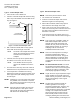
1. Use 1/2 inch PVC schedule 40.
2. Construct a tube as long as the inside width of
the hood.
3. With a 1/8-inch drill bit; drill 9 evenly spaced
holes down the entire length of the tube.
NOTE:
The holes in the sample tube should
always face towards the back of the hood
when the installation is complete.
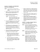
4. Mount the tube in the previously determined
position (where the mobile sampling tube gave
accurate readings).
NOTE:
For most fume hoods the tube can hang in
the middle and be attached to either
sidewall within the fume hood.
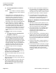
Type 2. For Horizontal Fume Hoods Only.
1. Use 1/2 inch PVC schedule 40.
2. If the fume hood has permanent bypass, then
attach the tube to the center of the bypass.
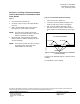
3. With a 1/8 inch drill bit; drill 9 holes evenly
spaced to ensure that all the sashes have the
same number of holes behind them. See Figure
2.
TOP VIEW OF FUME HOOD
ALL HOLES FACE THE REAR
1/4" HOLES 1/8" HOLES
FUM0246R1
SASHES
Figure 2. Sample Tube for Horizontal or Combination
Fume Hoods Only.
Location for the SideWall Adapter or Sample Tube is
complete.
The installation is now complete.