
Data Sheet for Product
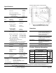
Table Of Contents

Information in this document is based on specifications believed correct at the time of publication. The right is reserved to make changes as design
improvements are introduced. APOGEE is a trademark of Siemens Building Technologies, Inc. © 2008 Siemens Building Technologies, Inc.
Siemens Building Technologies, Inc.
1000 Deerfield Parkway
Buffalo Grove, IL 60089-4513
Printed in the U.S.A. (origin)
Page 2 of 2
Specifications
Power
Supply
Operating Voltage
Frequency
Peak Load (at power up)
Maximum Operating Load (typ.):
Terminal Units
Venturi Air Valves
24Vac
(18-30)
50/60Hz
25 VA
12 VA
25 VA
Mounting
on rotating
shaft
Shaft size
½ in to ¾ in
(12.7mm to 19mm)
Minimum
shaft length
2.5 inches
(63.5mm)
Control
Signal
Input Signal
Floating (pulse)
Analog (0-10Vdc)
Voltage input
Input resistance
Analog (4-20mA)
Current input
Input resistance
15-35Vac or
10-47 Vdc
0-10Vdc
100 K Ohms
4-20mA
250 Ohms
Function
Stroke
2.75" (70mm)
Rotation / Crank Length
90
o
/
1.94" (49mm)
60
o
/ 2.75" (70mm)
45
o
/ 3.59" (91mm)
Maximum Thrust
50 lbf (220N)
Maximum Torque
97 in-lb(11.0 Nm)
137 in-lb(15.5 Nm)
179 in-lb(20.3 Nm)
Stroke time (end-to-end)
_1.8s (No Load) / 2.3s (Max Load)
Flow Response time
_< 1.0s for flow change of 5:1 using Siemens
Lab Exhaust Terminal or Venturi Air Valve
Enclosure
Material
18 gage Galv steel
Dimensions
See Figure 2
Ambient
Temperature
Operation
40 to 104 F
(5 to 40 C)
Transportation and
storage
15 to 140 F
(-9 to 60 C)
Humidity
5% to 95%
(non-condensing)
Misc.
Weight
Enclosed Assembly
Actuator Only
12.3 lbs. (5.6 kg)
3.0 lbs. (1.4 kg.)
US Patent
5,833,529
Agency Listings
UL Listing
cUL Listed
FCC Compliance
CE (including EN61326)
UL 916, PAZX,
Canadian Standards
C22.2 No. 205-M1983, PAZX7
47 CFR Part 15
Interface board requires an earth ground.
Figure 2. LEA Enclosed Assembly (5” deep)
Complete with Interface, Actuator, 90° crank
Operation
Floating control
Commands the actuator to extend
or retract using the proprietary
Siemens FHC/LRC pulsed control
signal or industry standard 3-
position pulsed signals.
0-10Vdc/4-20mA
0-10Vdc or 4-20mA control signal
controls the damper actuator. The
actuator stroke is proportional to
the control signal.
Power failure
Either maintain current position or
fail NO/NC. User selects the
appropriate failsafe position for
application.
Wiring
All wiring must conform to NEC and
local codes and regulations.
Product Ordering Information
Part No.
Lab Electronic Actuator (LEA)
Descriptions
Order For
546-00450
Interface Board (AO-E module)
546-00437B
LEA – Actuator Only
546-00581
LEA Bracket Kit, 90° rotation
546-00582
LEA Bracket Kit, 45°&60°rot.
NAILOR
ANEMOSTAT
546-00438
LEA Enclosed Assembly
TERMINAL
UNITS, 90°
V
E
N
T
U
R
I
T
E
R
M
I
N
A
L