
Installation Instructions

Document No. 546-00580
Installation Instructions
May 22, 2012
Page 4 of 7 Siemens Industry, Inc.
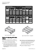
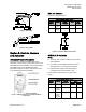
Table 2. Multi-Body Venturi Air Valve Dimensions.
Slip configuration (S & I)
Size
Matching Duct
Minimum Inside
Matching Duct Outside
Dimension
Face-to-
face
Length
(L
a)
1
)
Slip Tab
Length
Overall
Height with
Enclosure
Height
Width
Height (H)
Width (W)
2x10 10 21 11 22 29 1/2 1.5 19
2x12 12 25 13 26 32 1/2 1.5 21
3x12 12 38 13 39 32 1/2 1.5 21
Flange Configuration (F & J)
Size
Matching Duct
Minimum Inside
Matching Duct Outside
Dimension
Face-to-
face
Length
(L
a)
1
-3)
Overall
Height with
Enclosure
Height
Width
Height (H)
Width (W)
2x10 10 21 12 23
26 1/2
Flat
flange
No Holes
19
2x12 12 25 14 27
29 1/2
21
3x12 12 38 14 40
29 1/2
21
Slip end Air Valves need an extra 3 inches of clearance during installation.
a)
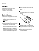
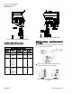
Figure 3: Dual Air Valve — Slip End.
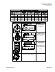
Figure 4:
Triple Air Valve — Flange End.
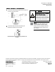
Section 2: Adjusting AVC Valve
Airflow
The control arm is held in place by a threaded rod
with two nuts on opposite sides of the flange on the
indicator gauge. To change the flow setting:
1.
Locate the nut on the upstream side of the
indicator gauge flange (side towards the inlet of
the air valve, where the flow sensor is located).
This is the calibration locking nut. Loosen this
nut and back it off to provide sufficient distance
to adjust the flow.
2. Locate the nut on the downstream side to move
the control arm. This is the flow adjustment nut.
Turning this nut clockwise reduces the airflow.
To increase the airflow rate, turn the flow
adjustment nut counter-clockwise.
3. Once the required airflow has been achieved,
tighten the calibration locking nut.