
Installation Instructions

Document No. 546-00580
Installation Instructions
May 22, 2012
Siemens Industry, Inc. Page 5 of 7
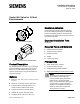
Figure 5: Style1 AVC.
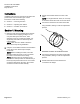
Figure 6:
Style 2 AVC.
Section 3: Controls, Sensors
and Actuation
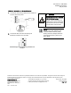
Differential Pressure Transmitter
Connect a two-conductor 20 AWG cable to the
controller’s 4 to 20 mA input. Connect the wire to the
differential pressure transmitter or through the wiring
bushing/knockout to the differential pressure
transmitter inside the enclosure. Connect the cable
to the differential pressure transmitter.
Figure 7:
Differential Pressure Transmitter Wiring
Connections.
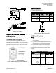
GMA 121 Actuation
2-position control, 24 Vac/dc.
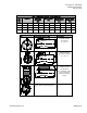
Table 4. 2-position Control 24 Vac.
Standard
Symbol
Function
Terminal
Designation
Color
Color
Symbol
1 Supply
(SP)
G Red RD
2 System
Neutral
G0 Black BK
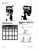
Figure 8:
GDE/GLB 131 Actuation
2-position GMA 121 Actuators.
Wiring
All wiring must conform to NEC and local codes
and regulations.
Use earth ground isolating step-down Class 2
transformers. Do not use auto transformers.
Three-position control (24 Vac), 24 Vac power
supply.
Determine the supply transformer rating by
summing total VA of all actuators used.
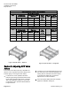
Table 5. 3-position Control 24 Vac.
Standard
Symbol
Function
Terminal
Designation
Color
Standard
Plenum
1 Supply (SP) G Red Red
6 Control
signal
clockwise
Y1 Violet Violet
7 Control
signal
counter-
clockwise
Y2 Orange Orange