
Installation Instructions

Document No. 546-00580
Installation Instructions
May 22, 2012
Page 6 of 7 Siemens Industry, Inc.
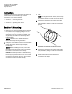
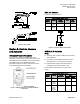
Figure 9:
GLB/GDE/GMA 161 Actuation
Actuator wiring for VAV/CV TECs.
Modulating control (0-10V), 24 Vac/dc.
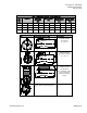
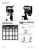
Table 6. Modulating Control 24 Vac.
Standard
Symbol
Function
Terminal
Designation
Color
Color
Symbol
1 Supply (SP) G Red RD
2 System
Neutral
G0 Black BK
8 Input
Signal:
0-10 Vdc
(GMA161)
or
2-10 Vdc
(GMA15x)
Y Gray GY
9 Position
Output: 0-
10 Vdc
(GMA161)
or 2-10 Vdc
(GMA15x)
U Pink PK
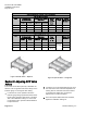
Figure 10:
GNP191 Actuation— Modulating Control (0
to 10 Vdc)
Actuator wiring for Basic LRC.
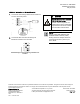
1. Connect the Fast Acting Lab Electronic Actuator
to a source of 24 Vac power.
2.
Connect the wire from the Fast Acting Lab
Electronic Actuator to the controller.
Supply
Exhaust
Switch Settings for the Fast Acting Lab Electronic
Actuator.