
Installation Instructions


Installation Instructions
Document No. 546-00092
August 10, 2011
Laboratory Electronic Actuator Assembly
Item No. 546-00092(HA) Page 1 of 6
Product Description
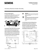
The Lab Electronic Actuator (Figure 1) is a compact,
high-speed actuator designed for modulating and
floating control of dampers or air valves. The
complete actuator consists of three parts: the Lab
Electronic Actuator, Mounting Bracket kits (90° OR
45°/60° rotation) and Interface Board.
Figure 1. Electric Actuator
The LEA Interface Board (also known as the Analog
Output-Electronic, AO-E board) powers and controls
motion the Actuator based on input signals. The
interface board supports floating (digital) 24VAC
pulses or analog 0-10vdc, and analog 4-20mA input
signals. Capacitors on the Interface Board provide
power for fail-safe positioning. Through the Interface
board, the actuator can be connected to the Fume
Hood Controller (FHC), Lab Room Controller (LRC)
or other DDC controllers with VAV lab applications
requiring high-speed actuator positioning.
Figure 2. LEA Interface Board.
WARNING:
Venturi Air Valves and Terminal Boxes (blade
dampers), all sizes draw 25 VA maximum per
LEA Interface board.
NOTE:
A three-wire power trunk must be run from the
transformer to the LEA Interface board for the
electronic actuator. The ‘E’ connection of
terminal block J1 must be connected to
ground.
The Lab Electronic Actuator Assembly (Figure 3)
includes the interface board, the actuator and the
90° Rotation Mounting Bracket kit installed in a
galvanized steel enclosure. The LEA enclosed
assembly can be field or factory mounted over the
bare shaft of any supply or exhaust terminal. When
mounting on terminals with their own device
enclosures, provide the three components and not
the Assembly. Be careful to select the mounting kit
that matches the terminal’s rotation.
Figure 3. Electronic Actuator Assembly for Terminal
Units.