
Installation Instructions

Installation Instructions
Document No. 546-00336
January 26, 2011
Laboratory Room Airflow Station
Item Number: 546-00336, Rev. 4 Page 1 of 3
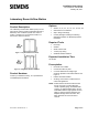
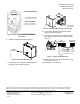
Product Description
The Laboratory Room Airflow Station (LGF) is a one-
piece device used to measure total airflow through a
laboratory room ventilation system duct. Refer to
Figure 1 and Figure 2. The terminal consists of a
duct sectio
n and a flow sensor.
Figure 1. Slip Ends Exhaust Terminal.
Figure 2. Flange Ends Exhaust Terminal.
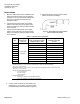
Product Numbers
Contact your Siemens Industry, Inc. representative
for detailed parts information.
Options
Sizes 4", 6", 8", 10", 12", 14", 16", 18", 20", 22"
Galvanized or 316 stainless
Slip or flange end fittings
Control packages including the following:
Offboard Air Module or differential pressure
transmitter.
Required Tools
Duct tape
Sealant
Sheet metal screws
1/4-inch poly tubing
Small flat-blade screwdriver
Expected Installation Time
30 minutes
Prerequisites
Ductwork free of debris
Construction filters in place
2-1/2 duct diameters of straight rigid
ductwork upstream of the airflow station. See
Figure 3.
Exhaust ductwork installed
All wiring must conform to NEC and local
codes and regulations.
NOTE: Airflow stations should be located so that
they do not come in contact with rigid
conduit, sprinkler piping, Greenfield metal
covering, or rigid pneumatic tubing. Do not
install airflow stations tight against concrete
slabs or columns because vibrations are
amplified through these structures. Also,
allow clearance for service access to
controls.