
Installation Instructions

Document No. 546-00336
Installation Instructions
January 26, 2011
Page 2 of 3
Siemens Industry, Inc.
Instructions
4.
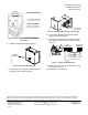
Seal all ductwork and check that the airflow
station connections are airtight.
1. Move the airflow station to the installation area.
Remove the
airflow station from the shipping
package. Do not carry the airflow station by the
flow sensor. Terminal measurements are
included in Table 1.
2.
Connect the exhaust ductwork to the airflow
station’s inlet collar using the accepted trade
practice of welding or bolting the airflow station
to the ductwork.
3. Connect the exhaust ductwork to the airflow
station’s outlet collar using the accepted trade
practice of welding or bolting the airflow station
to the ductwork.
Figure 3. Airflow Station Properly Installed
after an Elbow Duct Section.
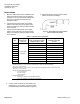
Table 1. LGF Dimensions by Unit Size.
Duct
Size
Length
Inches (mm)
+ 0.06 (1.5)
Slip End Outside Diameter
(O.D.) or Flange End Inside
Diameter (I.D.) In. (mm)
Flange
Bolt Hole Circle Size
In. (mm)
4 3.88 (98.6) 5.315 (135)
6 5.88 (149.4) 7.375 (187.3)
8 7.88 (200.2) 9.5625 (242.9)
10 9.88 (251.0) 11.8125 (300)
12 11.88 (301.8) 14 (355.6)
14 13.88 (352.6) 16 (406.4)
16 15.88 (403.4) 18 (457.2)
18 17.88 (454.2) 20 (508)
20 19.88 (505.0) 22 (552.8)
22
8.00 Inches
(203 mm)
21.88 (555.8) 24 (609.6)
Provide a minimum of 2.5 duct diameters of straight rigid duct directly upstream.
Flanged connection is 1.0” (25.4 mm) for all 4” through 10” sizes and 12” BA assemblies.
OD = O.D. + 2.0” (50.8 mm)
Flanged connection is 1.5” (38.1 mm) for 12” AA, AB, and CA assemblies and all 14” through 22” sizes.
OD = O.D. + 3.0” (72.2 mm).
Flanged connection Bolt Hole Quanitity:
6 for 4” through 12”
8 for 14” and 16”
10 for 20” and 22”
Flanged Bolt Hole Size:
0.4375” for 4” through 14” and all BA assemblies
0.5” for 16” through 22” AA, AB, and CA assemblies
5. Connect a two-conductor 20 AWG cable to the
field panel’s 4 - 20 mA input. Connect the cable
to the differential pressure transmitter (Figure 4).