
Installation Instructions

Document No. 546-00336
Installation Instructions
January 26, 2011
Information in this document is based on specifications believed correct at the time of publication. The right is reserved to make changes as
design improvements are introduced. APOGEE and Insight are registered trademarks of Siemens Industry, Inc. Other product or company
names mentioned herein may be the trademarks of their respective owners. © 2011 Siemens Industry, Inc.
Siemens,Industry Inc.
Building Technologies Division
1000 Deerfield Parkway
Buffalo Grove, IL 60089-4513
U.S.A.
Your feedback is important to us. If you have
comments about this document, please send
them to
SBT_technical.editor.us.sbt@siemens.com.
Document No.: 546-00336
Printed in the U.S.A.
Page 3 of 3
Figure 4. Differential Pressure Transmitter Wiring
Connections.
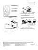
6. Install the Offboard Air Module (Figure 5).
TUBING
CONNECTIONS
TEC0464R2
LO
HI
Figure 5. Offboard Air Module (OAM).
7. Remove the cover. Install the conduit adapter in
the wiring hole if required (Figure 6).
TEC0465R2
LO
HI
HOLE FOR WIRING
TO PASS THROUGH
Figure 6. Offboard Air Module with Cover Removed.
8. Run Autozero Module and Air Velocity Sensor
wiring through the wiring hole.
9. Wire up the terminal block on the OAM. Terminal
block plug(s) can be removed for easier access
(Figure 7).
TEC0530R2
PPGGO
15 16
TO CONTROLLER D.O. FOR AZM
NOTE THE REVERSAL OF O, G, P ORDER
O
AVS INPUT AT
CONTROLLER
OAM
TERMINATIONS
OUTPUT SIGNAL
GROUND
POWER
Figure 7. Offboard Air Module Wiring.
10. Replace the cover and connect pneumatic tubing
(Hi to Hi and Lo to Lo).
The installation is now complete.