
Application

Sequence of Operation
VAV versus CV Control
12
Siemens Industry, Inc.
Application Note, App 2922
140-1301
2015-07-07
When OCC.UNOCC equals UNOCC:
The active supply airflow minimum equals UOC SUP MIN.
The active supply airflow maximum equals UOC SUP MAX.
The active general exhaust airflow minimum equals UOC GEX MIN.
The active general exhaust airflow maximum equals UOC GEN MAX.
VAV versus CV Control
In Application 2922, VAV means that temperature is controlled by varying flow in
conjunction with the reheat valve. CV means that temperature is controlled by using
the reheat valve only. The supply and general exhaust can still change in CV mode to
keep the volume differential setpoint constant. This may be necessary if HOOD VOL is
varying. Application 2922 can do VAV or CV control and can also change the type of
air volume control based on which mode it is operating in (OCC or UNOCC).
When OCC.UNOCC equals
OCC, Application 2922 will perform VAV control
provided that VOLUME STATE equals
1 or 3. It will perform constant volume (CV)
control provided that VOLUME STATE equals
0 or 2.
When OCC.UNOCC equals
UNOCC, Application 2922 will perform VAV control
provided that VOLUME STATE equals
2 or 3. It will perform constant volume
control provided that VOLUME STATE equals
0 or 1.
Depending on how VOLUME STATE is configured, Application 2922 can operate as
either a Variable Air Volume (VAV) LCM or a constant volume (CV) LCM. Also, these
operational modes can vary between the occupied and unoccupied periods, if desired.
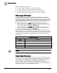
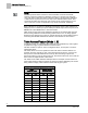
The following table shows what the application does when VOLUME STATE is at a
particular value.
VOLUME STATE Values.
VOLUME STATE
(value)
Description
0
Always Constant Volume.
1
(default)
VAV during occupancy, Constant Volume during unoccupied period.
2
Constant Volume during occupancy, VAV during unoccupied period.
3
Always VAV.
NOTE:
If VOLUME STATE is set greater than 3, it will default to 0.
Fume Hood Flow Input
A signal of 1 to 10 Vdc at AI 3 represents the volume of air that is exhausted through
the fume hood(s). By using a Fume Hood Flow Module (FFM), you can connect up to
six fume hoods to AI 3. Multiple fume hood flows must be averaged using a Fume
Hood Flow Module. The resulting airflow is displayed in point HOOD VOL.
MAX HOOD VOL is set during start-up to indicate the flow in cubic feet per minute
(cfm) that corresponds to an input signal of 10 Vdc. A signal of 1 Vdc indicates 0 cfm. If
the signal drops below 1 Vdc, TOTL EXHAUST will fail.