
Basic Documentation
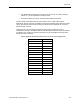
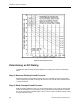

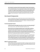

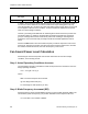

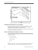
Table Of Contents
- About this Application Guide
- Chapter 1–Introduction
- Chapter 2–Physics of Sound
- Chapter 3–HVAC Sound Sources
- Chapter 4–HVAC Sound Attenuation
- Introduction to HVAC Sound Attenuation
- Plenums
- Duct Attenuation
- Duct Takeoffs and Divisions
- Duct Silencers
- End Reflection
- Environment Adjustment Factor
- Space Effect
- Radiated Sound Attenuation
- Chapter 5–HVAC System Sound Analysis
- Chapter 6–Minimizing HVAC Sound
- Appendix
- Glossary
- Index

Chapter 3–HVAC Sound Sources
Fan Type
63H
z
125H
z
250H
z
500H
z
1kH
z
2kH
z
4kH
z
8kH
z
BFI
Propeller All Sizes 48 51 58 56 55 52 46 42 5
In Table 5, the sound power levels listed are quite low with respect to those listed in Table 1
for sources of sound. However, the values in Table 5 are only a starting point. They only
cover fan operation at 1 cfm and 1.00 inches water static pressure (wsp). Since no fan would
ever be applied under this set of conditions, we must calculate the expected sound power
level at our actual design conditions.
However, just looking at this table tells us something about which fans tend to produce less
sound than others. For instance, centrifugal fans are quieter than axial fans, and the top
group of centrifugal fans has the lowest sound power level. Radial type centrifugal fans
produce the most sound and really are really intended for industrial applications and not
HVAC.
Note that the BFI column refers to the blade frequency increment component of the sound
power level. The lower the number, the lower this sound component will be. Also, the fewer
the number of blades the fan has, the lower the frequency of the sound.
Fan Sound Power Level Calculation
Determining the actual sound power level at each octave band for a fan at its design
conditions, is a three-step process.
Step 1. Actual Operating Conditions Increase
Use the following formula to calculate the actual sound pressure level increase for the fan’s
design operating conditions:
FLw = 10 Log Q + 20 Log P
Where:
FLw = the fan sound power level increase.
Q = the design airflow rate (cfm).
P = the design fan static pressure (in. WC).
Step 2. Blade Frequency Increment (BFI)
Determine that the octave band the Blade Frequency Increment (BFI) should be added. The
formula below yields the frequency (Hz) at which this blade sound component will occur.
Hz = Fan RPM ÷ 60 x Number of Blades
26 Siemens Building Technologies, Inc.