
Basic Documentation
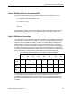
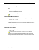
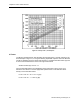


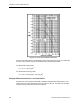
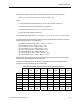

Table Of Contents
- About this Application Guide
- Chapter 1–Introduction
- Chapter 2–Physics of Sound
- Chapter 3–HVAC Sound Sources
- Chapter 4–HVAC Sound Attenuation
- Introduction to HVAC Sound Attenuation
- Plenums
- Duct Attenuation
- Duct Takeoffs and Divisions
- Duct Silencers
- End Reflection
- Environment Adjustment Factor
- Space Effect
- Radiated Sound Attenuation
- Chapter 5–HVAC System Sound Analysis
- Chapter 6–Minimizing HVAC Sound
- Appendix
- Glossary
- Index

Fan Sound Power Level Calculation
Step 2. Blade Frequency Increment (BFI)
Using the Hz formula, the frequency at which the blade sound component will occur is:
Hz = Fan RPM x (Number of Blades ÷ 60)
Hz = 1300 x (10 ÷ 60)
Hz = 1300 x (0.167)
Hz= 217
Referring back to Table 6, since 217 Hz is within the 250 Hz octave band, the BFI value of 3
dB (obtained from the rightmost column of Table 5) is added to the 250 Hz octave band
column in our summary chart on the next page.
Step 3. Efficiency Correction
Let’s assume that our overall HVAC system design is based upon an operating fan efficiency
of at least 90%. In other words, with reference to Figure 8, the operating point will be on the
centrifugal fan curve slightly to the right of the peak. In this area, there is no need to add any
decibels to correct off peak fan efficiency. However, since there’s always the likelihood of
actual conditions resulting in operation at less than our theoretical efficiency, in this case,
we’ll add 3 dB to be on the safe side with our calculations. The sound power level decibels in
the above chart are more in line with what we might expect with reference to the fan typical
sound power levels as indicated back in Table 1. In fact, they may seem to be quite high and
pose a real problem, but they’re actually quite normal in view of typical HVAC fans.
Table 8. Sound Calculation Summary for Actual Fan Operating Conditions.
63 125 250 500 1,000 2,000 4,000 8,000
Hz Hz Hz Hz Hz Hz Hz Hz
Table 5
45 45 43 39 34 28 24 19
Step 1
(FLw)
54 54 54 54 54 54 54 54
Step 2
(BFI)
— — 3.0 — — — — —
Step 3
(EFF)
3.0 3.0 3.0 3.0 3.0 3.0 3.0 3.0
Final
102 dB 102 dB 103 dB 96 dB 91 dB 85 dB 81 dB 76 dB
The resulting sound pressure level in rooms served by the HVAC system will be attenuated
to some extent by the ductwork itself and other duct components and may result in an
acceptable sound pressure level in the rooms served. However, any good designer must
determine what attenuation will likely occur in the system and if additional attenuation must
be added.
Siemens Building Technologies, Inc. 29