
Basic Documentation
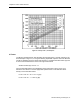


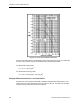

Table Of Contents
- About this Application Guide
- Chapter 1–Introduction
- Chapter 2–Physics of Sound
- Chapter 3–HVAC Sound Sources
- Chapter 4–HVAC Sound Attenuation
- Introduction to HVAC Sound Attenuation
- Plenums
- Duct Attenuation
- Duct Takeoffs and Divisions
- Duct Silencers
- End Reflection
- Environment Adjustment Factor
- Space Effect
- Radiated Sound Attenuation
- Chapter 5–HVAC System Sound Analysis
- Chapter 6–Minimizing HVAC Sound
- Appendix
- Glossary
- Index

Damper Airflow Noise
C = 15.9 x 10
6
DP S
2
÷ Q
2
Where:
DP = the pressure drop across the damper from the manufacturer’s data.
S = the duct area at the damper in square feet
Q = the CFM.
In lieu of S
2
/Q
2
, the term 1/V
2
may be substituted, where V is the air velocity in feet/minute.
Calculate Damper Blockage Factor BF
To calculate damper blockage factor BF for a multi-blade damper, use the following formula:
If C ≠ 1, BF = (C
½
-1) ÷ (C - 1)
If C = 1, BF = 0.5
To calculate damper blockage factor BF for a single-blade damper, use the following formula:
If C < 4, BF = C
0.5
- 1) ÷ (C - 1)
If C > 4, BF = (0.68 x C
-0.15
) - 0.22
Calculate the Velocity Factor U
To calculate the velocity factor U, use the following formula:
U = (Q ÷ S) ÷ BF
In lieu of Q/S, the term V may be substituted, where V is the air velocity in feet/minute.
The graph in Figure 9 provides Velocity Factor values for dampers within common airflow
ranges and pressure drops. Using the graph eliminates the need to go through the foregoing
three equations to calculate U.
Siemens Building Technologies, Inc. 31