
Basic Documentation
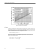


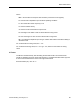
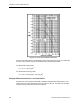
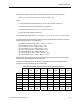

Table Of Contents
- About this Application Guide
- Chapter 1–Introduction
- Chapter 2–Physics of Sound
- Chapter 3–HVAC Sound Sources
- Chapter 4–HVAC Sound Attenuation
- Introduction to HVAC Sound Attenuation
- Plenums
- Duct Attenuation
- Duct Takeoffs and Divisions
- Duct Silencers
- End Reflection
- Environment Adjustment Factor
- Space Effect
- Radiated Sound Attenuation
- Chapter 5–HVAC System Sound Analysis
- Chapter 6–Minimizing HVAC Sound
- Appendix
- Glossary
- Index

Damper Airflow Noise
Figure 10. Characteristic Spectrum K vs. Strouhal Number for Dampers.
Example of Damper Sound Power Level Calculation
Assume a rectangular opposed blade control damper is to be used to control duct static
pressure in a 48 inches wide x 24 inches high supply system duct. The system is designed to
provide 20,000 cfm at a 0.3 in. WC gauge pressure drop across the damper. Determine the
sound power level that the damper will produce under these conditions.
Determine the values for the terms in the Damper Sound Power Level (DLw) formula:
DLw = K + 10 Log F + 50 Log U + 10 Log S+ 10 Log D -107 dB
Where:
F = the octave band center frequency in Hz: (63, 125, 250, 500, 1,000, etc.).
U = the damper Velocity Factor: (Duct Air Velocity = 20,000 cfm/8 sq. ft.
= 2,500 ft/min)
From Figure 10, U = 4,650.
S = the duct area square feet at the damper location: (4 ft x 2 ft = 8 sq ft).
D = the duct height in feet (2 ft).
Siemens Building Technologies, Inc. 33