
Basic Documentation
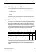
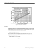


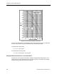
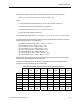

Table Of Contents
- About this Application Guide
- Chapter 1–Introduction
- Chapter 2–Physics of Sound
- Chapter 3–HVAC Sound Sources
- Chapter 4–HVAC Sound Attenuation
- Introduction to HVAC Sound Attenuation
- Plenums
- Duct Attenuation
- Duct Takeoffs and Divisions
- Duct Silencers
- End Reflection
- Environment Adjustment Factor
- Space Effect
- Radiated Sound Attenuation
- Chapter 5–HVAC System Sound Analysis
- Chapter 6–Minimizing HVAC Sound
- Appendix
- Glossary
- Index

Chapter 3–HVAC Sound Sources
K requires solving for the Strouhal number at each octave band center frequency and then
using the graph in Figure 10 to determine K.
St = 60FD÷ U
St= 60 x 63 Hz x 2 ft. ÷ 4,650 = 1.6, K = -39
St= 60 x 125 Hz x 2 ft. ÷ 4,650 = 3.2, K = -42
St= 60 x 250 Hz x 2 ft. ÷ 4,650 = 6.4, K = -45
St= 60 x 500 Hz x 2 ft. ÷ 4,650 = 12.8, K = -48
St= 60 x 1,000 Hz x 2 ft. ÷ 4,650 = 25.6, K = -52
St= 60 x 2,000 Hz x 2 ft. ÷ 4,650 = 51.2, K = -63
St= 60 x 4,000 Hz x 2 ft. ÷ 4,650 = 102.4, K = -75
St= 60 x 8,000 Hz x 2 ft. ÷ 4,650 = 204.8, K = -86
Note that after the first St number is calculated, the remaining seven values can be quickly
determined by just doubling the previous St value.
Table 8 summarizes the terms and results of using the DLw formula to determine the net
sound power level of this damper at each octave band.
Note in Table 8 that since the DLw values are all positive, the damper has the potential for
adding to the net sound power level produced by the HVAC system. However, if this damper
was located within a short distance from the fan example of a few pages earlier, the net
change in the total sound power level would not perceptibly change since the fan’s sound
power level was significantly higher than this damper by approximately 25 to 35 dB
throughout all of the octave bands. See Table 3 for adding sound power or sound pressure
levels.
On the other hand, if this damper were near a room served by the HVAC system, and the fan
sound had already been substantially attenuated (lessened), the sound power level
generated by this damper could have a significant impact on the sound pressure level in the
room.
Keep in mind that control devices such as dampers should be located as far as possible
upstream to minimize their effect on the overall HVAC system sound power level.
Elbow Airflow Noise
Elbows generate aerodynamic sound and also attenuate a certain amount of aerodynamic
sound. The resultant will either be a net gain or reduction in sound pressure level, depending
upon the airflow velocity through the elbow, pressure drop and several other factors. Like the
previous discussion on fan and damper sound power, it is necessary to determine the actual
sound power level at each octave band for an elbow at the HVAC system’s design operating
conditions.
The following formula will provide the actual sound power level increase or decrease at each
octave band for an elbow between two sections of the same size of duct:
ELw = K + 10 Log F + 50 Log U + 10 Log S+ 10 Log D + EC
34 Siemens Building Technologies, Inc.