
Basic Documentation
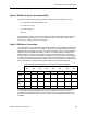
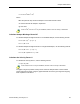


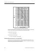
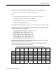

Table Of Contents
- About this Application Guide
- Chapter 1–Introduction
- Chapter 2–Physics of Sound
- Chapter 3–HVAC Sound Sources
- Chapter 4–HVAC Sound Attenuation
- Introduction to HVAC Sound Attenuation
- Plenums
- Duct Attenuation
- Duct Takeoffs and Divisions
- Duct Silencers
- End Reflection
- Environment Adjustment Factor
- Space Effect
- Radiated Sound Attenuation
- Chapter 5–HVAC System Sound Analysis
- Chapter 6–Minimizing HVAC Sound
- Appendix
- Glossary
- Index

Chapter 3–HVAC Sound Sources
In Table 9, the ELw values are all positive, so this elbow adds to the sound power level
produced by the HVAC system. If this elbow was located within a short distance from the
Example Fan Sound Power Level Calculation, the net change in the total sound power level
would not perceptibly change since the fan’s sound power level was significantly higher by a
range of 16 to 51 dB throughout the octave bands. On the other hand, if this elbow were near
a room served by the HVAC system, the sound power level could have a very significant
impact on the sound pressure level in the room since this elbow generates significant sound
power in the lower frequency octaves.
Junction and Takeoff Airflow Noise
Just as dampers and elbows have the ability to add to or attenuate the sound power level, so
do junctions and takeoffs. The resultant may be a net gain or reduction in sound pressure
level, depending upon the airflow velocity, pressure drop and several other factors. Like the
previous discussions on fan, damper, and elbow sound power levels, it is necessary to
determine the actual sound power level at each octave band for a junction or takeoff at the
HVAC system’s design operating conditions.
The following formula will provide the actual sound power level increase or decrease at each
octave band for a duct junction or takeoff:
JLw = K + 10 Log F + 50 Log U
B
+ 10 Log S + 10 Log D - JC
Where:
Elw = the net sound power level increase (or decrease if it is negative).
K = an factor dependent upon design conditions.
F = the octave band center frequency in Hz.
U
B
= the branch duct airflow velocity.
S = the branch duct cross sectional area in square feet.
D (for Takeoffs) = branch duct height in feet.
D (for Junctions) = (4S/π)
0.5
feet.
K Factor
The K factor is determined by first calculating the Strouhal number. Since the Strouhal
number is dependent upon the octave band frequency, a separate Strouhal number (St) and
K factor must be determined for each of the eight octave bands.
Strouhal number (St) = 60 F D ÷ U
B
38 Siemens Building Technologies, Inc.