
Basic Documentation
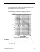

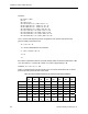


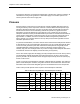
Table Of Contents
- About this Application Guide
- Chapter 1–Introduction
- Chapter 2–Physics of Sound
- Chapter 3–HVAC Sound Sources
- Chapter 4–HVAC Sound Attenuation
- Introduction to HVAC Sound Attenuation
- Plenums
- Duct Attenuation
- Duct Takeoffs and Divisions
- Duct Silencers
- End Reflection
- Environment Adjustment Factor
- Space Effect
- Radiated Sound Attenuation
- Chapter 5–HVAC System Sound Analysis
- Chapter 6–Minimizing HVAC Sound
- Appendix
- Glossary
- Index

Chapter 3–HVAC Sound Sources
Where:
Δr = Junction Radius/Branch Duct Diameter.
= r ÷ D
BR
Note that for duct junctions and takeoffs without a radius, Δr is 0.0. However for duct
junctions and takeoffs with a radius, Δr is greater than zero, and reduces the sound power
level generated at the junction.
For junctions and takeoffs with a radius, the Δr values must be corrected for each octave
band. This requires taking the Strouhal number (already calculated for the K factors) for each
octave band and also the value of r ÷ D
BR
, then using Figure 13 to arrive at the final corrected
Δr values for each octave band.
The turbulence factor of ΔT applies if there are other duct elements within five duct diameters
upstream of the main junction or takeoff. After calculating M, Table 10 gives values for ΔT.
Table 10. Upstream Turbulence Factor Values for Junctions and Takeoffs
Example Duct Takeoff Sound Power Level Calculation
Determine the net sound power level that will result from a 12-foot square duct takeoff from a
36 inch wide x 24 inch high main supply system duct. The main duct supplies 14,500 cfm
while the takeoff duct is intended to provide a maximum of 1,600 cfm to a VAV box. The
takeoff uses is a standard 45 degree converging tee (no radius) duct element. There is also a
normally open smoke damper approximately eight feet upstream from this takeoff.
40 Siemens Building Technologies, Inc.