
Basic Documentation
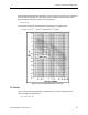

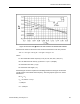
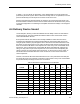


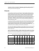
Table Of Contents
- About this Application Guide
- Chapter 1–Introduction
- Chapter 2–Physics of Sound
- Chapter 3–HVAC Sound Sources
- Chapter 4–HVAC Sound Attenuation
- Introduction to HVAC Sound Attenuation
- Plenums
- Duct Attenuation
- Duct Takeoffs and Divisions
- Duct Silencers
- End Reflection
- Environment Adjustment Factor
- Space Effect
- Radiated Sound Attenuation
- Chapter 5–HVAC System Sound Analysis
- Chapter 6–Minimizing HVAC Sound
- Appendix
- Glossary
- Index

Chapter 3–HVAC Sound Sources
Therefore:
M = 2,420 ÷ 1,600
M = 1.5
St = 60 F D ÷ U
B
St = 60 x 63 Hz x 1 ft ÷ 1,600 = 2.4, K = -11
St =60 x 125 Hz x 1 ft ÷ 1,600 = 4.7, K = -18
St =60 x 250 Hz x 1 ft ÷ 1,600 = 9.4, K = -24
St = 60 x 500 Hz x 1 ft ÷ 1,600 = 18.8, K = -30
St = 60 x 1,000 Hz x 1 ft ÷1,600 = 37.5, K = -40
St = 60 x 2,000 Hz x 1 ft ÷1,600 = 75.0, K = -49
St = 60 x 4,000 Hz x 1 ft ÷ 1,600 = 150.0, K = -57
St = 60 x 8,000 Hz x 1 ft ÷ 1,600 = 300.0, K = -68
JC is a constant that depends upon the configuration of the junction and relates to the
junction’s ability to attenuate sound.
JC = -107 + Δr + ΔT
Δr = Junction Radius/Branch Duct Diameter
= r ÷ D
BR
r = 0 and r ÷ D
BD
= 0
= 0 ÷ 0
= 0
Since there is upstream turbulence (a smoke damper) within five main duct diameters, Table
10 is used with the 1.5 value for M to obtain a ΔT value of approximately 1 dB.
Therefore, JC = -107 + 0 + 1 = -106
Table 11 summarizes the terms and results of the JLw formula to determine the net sound
power level of this junction at each octave band.
Table 11. Sound Calculation Summary for Actual Fan Operating Conditions.
63 125 250 500 1,000 2,000 4,000 8,000
Hz Hz Hz Hz Hz Hz Hz Hz
K -11 -18 -24 -30 -40 -49 -57 -68
10 Log F 18 21 24 27 30 33 36 39
50 log U 160 160 160 160 160 160 160 160
10 Log S 0 0 0 0 0 0 0 0
10 Log D 0 0 0 0 0 0 0 0
JC -106 -106 -106 -106 -106 -106 -106 -106
JLw 61 57 54 51 44 38 33 25
dB dB dB dB dB dB dB dB
42 Siemens Building Technologies, Inc.