
Basic Documentation

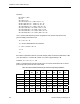


Table Of Contents
- About this Application Guide
- Chapter 1–Introduction
- Chapter 2–Physics of Sound
- Chapter 3–HVAC Sound Sources
- Chapter 4–HVAC Sound Attenuation
- Introduction to HVAC Sound Attenuation
- Plenums
- Duct Attenuation
- Duct Takeoffs and Divisions
- Duct Silencers
- End Reflection
- Environment Adjustment Factor
- Space Effect
- Radiated Sound Attenuation
- Chapter 5–HVAC System Sound Analysis
- Chapter 6–Minimizing HVAC Sound
- Appendix
- Glossary
- Index

Chapter 3–HVAC Sound Sources
There will be little opportunity for sound attenuation after the diffuser. Many air diffusers are
available with an integral throttling damper as part of the diffuser. Since the throttling damper
has the potential for generating airflow sound, this must also be taken into account with
reference to the air diffuser’s sound rating. Therefore, whenever a diffuser has a throttling
damper in its collar, the following increases to the dB values in Table 9 apply:
+5 dB for a 0.05-inch throttling damper pressure drop
+10 dB for a 0.15-inch throttling damper pressure drop
+15 dB for a 0.25-inch throttling damper pressure drop
Since a device such as a VAV terminal, is normally located above a room’s ceiling and also
uses additional ductwork to connect to the air diffusers, there is some potential for sound
attenuation of a terminal’s sound pressure level by its diffuser ductwork. However, since air
diffusers are typically the last element on the HVAC system, they should be selected based
upon an NC rating that does not exceed the room’s NC rating, since there will be little
opportunity for sound attenuation after the diffuser.
Flexible Duct Connection to Diffusers
Designers should incorporate a notation on the mechanical plans wherever flexible duct is
permitted to connect air terminal units to room supply diffusers, to avoid creating additional
diffuser sound due to the air turbulence caused by the duct offset. Centerline offsets greater
than 1/8 of the diffuser collar diameter for each equivalent collar length will begin to
appreciably add to the diffuser NC rating, and can ultimately result in increases of up to 12
dB.
Likewise, any turbulence inducing device such as a balancing damper should be located as
far as practical (that is, 10 duct diameters) upstream of the diffuser to avoid possible
increased diffuser sound.
Discharge Sound and Radiated Sound
So far, we have discussed how sound travels through a duct system and is eventually
discharged into a space. Aside from this type of sound transmission, sound can also be
transmitted as HVAC radiated sound into a space. Radiated sound is when a sound source
produces sound waves that travel directly to the listener, (through the air or through ceilings
and walls) without using the ductwork as a conduit. The whine and rumble of a HVAC fan that
is heard when inside of an equipment room is sound that is radiated directly to the listener.
Room terminal units, especially fan powered boxes, also radiate sound that can be heard by
a room occupant if the acoustical attenuation of the ceiling material and the room is not
sufficient to absorb the radiated sound power. Manufacturer’s data for terminal units should
provide sound ratings for radiated sound and discharge sound. The section on sound
attenuation will cover how to account for the effects of both radiated and discharge sound.
44 Siemens Building Technologies, Inc.