
Basic Documentation
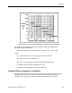
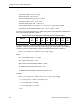
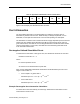


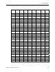
Table Of Contents
- About this Application Guide
- Chapter 1–Introduction
- Chapter 2–Physics of Sound
- Chapter 3–HVAC Sound Sources
- Chapter 4–HVAC Sound Attenuation
- Introduction to HVAC Sound Attenuation
- Plenums
- Duct Attenuation
- Duct Takeoffs and Divisions
- Duct Silencers
- End Reflection
- Environment Adjustment Factor
- Space Effect
- Radiated Sound Attenuation
- Chapter 5–HVAC System Sound Analysis
- Chapter 6–Minimizing HVAC Sound
- Appendix
- Glossary
- Index

Plenums
Figure 14. Relative Sound Absorbing Capabilities of Various Plenum Lining Material.
The following is a simplified formula that can be used to determine the approximate
attenuation a plenum will provide:
Plenum attenuation dB = Lf + {-10 Log [Ae (1 ÷ 6.283 d
2
) + Ae (1 -a)/(a * Aw)]}
Where:
Lf = Low frequency factor: 7 at 63 Hz, 6 at 125 Hz, and 1 at 250 Hz.
Ae = Area of plenum exit in square feet.
Aw = Area of sound absorption material on plenum walls in square feet.
d = Distance between the plenum inlet and exit in feet.
a = Material sound absorption coefficient (from Table 13).
Example Plenum Attenuation Calculation
Assume a plenum that is 10 feet long by 6 feet high and 6 feet wide is lined with 2-inch thick
fiberglass. If the fan inlet at one end is 3 feet square and the supply duct outlet at the
opposite end is 3 feet by 4 feet, determine what the expected attenuation would be.
Siemens Building Technologies, Inc. 49