
Basic Documentation
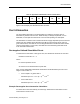

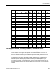

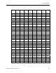
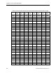
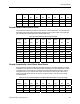
Table Of Contents
- About this Application Guide
- Chapter 1–Introduction
- Chapter 2–Physics of Sound
- Chapter 3–HVAC Sound Sources
- Chapter 4–HVAC Sound Attenuation
- Introduction to HVAC Sound Attenuation
- Plenums
- Duct Attenuation
- Duct Takeoffs and Divisions
- Duct Silencers
- End Reflection
- Environment Adjustment Factor
- Space Effect
- Radiated Sound Attenuation
- Chapter 5–HVAC System Sound Analysis
- Chapter 6–Minimizing HVAC Sound
- Appendix
- Glossary
- Index

Chapter 4–HVAC Sound Attenuation
Area of the outlet is: 3 ft x 4 ft = 12 ft
2
Area of the inlet is: 3 ft x 3 ft = 9 ft
2
Area of each plenum end is: 6 ft x 6 ft = 36 ft
2
Net Area of outlet is: 36 ft
2
- 12 ft
2
= 24 ft
2
Net Area of inlet end is: 36 ft
2
- 9 ft2 = 27 ft
2
Area of plenum sides is: 12 ft x (6 ft + 6 ft + 6 ft + 6 ft) = 12 ft x (24 ft) = 288 ft
2
Total plenum acoustically lined area is: 24 ft
2
+ 27 ft
2
+ 288 ft
2
= 339 ft
2
From the 2-inch Thick Fiberglass row in Table 13 we get the sound absorption coefficients for
each octave band as indicated in Table 14.
Table 14. Plenum Sound Absorption Coefficients for 2-inch Thick Fiberglass.
Material 63 125 250 500 1,000 2,000 4,000 8,000
Hz Hz Hz Hz Hz Hz Hz Hz
2-in. Thick Fiberglass 0.18 0.22 0.82 1.00 1.00 1.00 1.00 1.00
The approximate dB attenuation for each octave band is determined by taking the sound
absorption coefficient for each octave band and using the preceding formula. The calculation
is shown for the 63 Hz band and the results for the other bands are listed in Table 15.
dB = Lf + {-10 Log [Ae (1 ÷ 6.283 d
2
) + Ae (1 - a)/(a * Aw)]}
Where:
Lf = Low frequency factor: = 7 at 6 Hz.
Ae = Area of plenum exit: = 12 ft
2.
Aw = Area of sound absorption material: = 339 ft
2.
d = Distance between the plenum inlet: = 10 ft.
a = Material sound absorption coefficient at 63 Hz: = 0.18.
Therefore:
dB =7 + {-10 Log [12 x (1 ÷ 6.283 x 10
2
) +12 x (1 -0.18) ÷ (0.18 x 339)]}
= 7 + {-10 Log [12 x (1 ÷ 628.3) +12 x (0.82 ÷ 61)}
= 7 + {-10 Log [0.0191 + 0.1613]}
= 7 + {-10 Log [0.18]} = 7 + (7.439)
= 14.4
50 Siemens Building Technologies, Inc.