
Basic Documentation
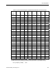
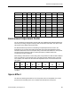


Table Of Contents
- About this Application Guide
- Chapter 1–Introduction
- Chapter 2–Physics of Sound
- Chapter 3–HVAC Sound Sources
- Chapter 4–HVAC Sound Attenuation
- Introduction to HVAC Sound Attenuation
- Plenums
- Duct Attenuation
- Duct Takeoffs and Divisions
- Duct Silencers
- End Reflection
- Environment Adjustment Factor
- Space Effect
- Radiated Sound Attenuation
- Chapter 5–HVAC System Sound Analysis
- Chapter 6–Minimizing HVAC Sound
- Appendix
- Glossary
- Index

Chapter 4–HVAC Sound Attenuation
Duct Silencers
Conventional duct silencers consist of prefabricated arrangements of sound absorbing
material intended for insertion within a duct run to attenuate sound. They offer only limited
attenuation in the low frequency (125 Hz and below) octave bands, and moderate attenuation
at the high frequency bands. Their maximum attenuation is in the mid frequency (that is,
1,000 Hz) octave bands. Apart from the extra cost of silencers, they also require a certain
amount of physical space and create additional pressure drop.
If a duct silencer is added to a duct run, the silencer will provide a certain attenuation or
insertion loss of the sound power level generated upstream. However, like any duct fitting, a
silencer also generates some sound power of its own. Therefore, aside from applying the
attenuation provided by a silencer to the sound power level, also determine if the sound
power generated by the silencer will have an appreciable impact on the net sound power
level.
Consult the manufacturer’s data sheets for the attenuation and sound power level generation
data for a given silencer. Also be sure to follow the manufacturer’s instructions regarding the
proper installation and location for a silencer. For proper functionality, there should be a
certain minimum distance, equivalent to a number of duct diameters, between the discharge
of a fan and the silencer, and between the silencer and other duct elements (elbows, etc.).
End Reflection
When ducts terminate into a ceiling air diffuser that discharges air into a room, a significant
amount of low frequency sound energy is reflected back into the ductwork. This phenomenon
is referred to as end reflection. The effect of duct end reflection is estimated by the following
formula:
Attenuation = 10 Log [1 + (3453 ÷ F D)
1.88
]
D = Diameter (inches) for round ducts
D = (1.27 x Area in.
2
)
½
for rectangular ducts
Table 24 lists end reflection attenuation values for round and square ducts based upon this
formula.
Table 24. End Reflection Attenuation for Typical Room Discharge Size Ducts.
Duct 63 125 250 500 1,000 2,000 4,000 8,000
Size Hz Hz Hz Hz Hz Hz Hz Hz
6 in. dia. 18.1 12.7 7.6 3.6 1.3 0.4 0 0
8 in. dia. 15.8 10.5 5.7 2.5 0.8 0.2 0 0
10 in. dia. 14.0 8.9 4.5 1.8 0.6 0.1 0 0
12 in. dia. 12.6 7.6 3.6 1.3 0.4 0 0 0
62 Siemens Building Technologies, Inc.