
Basic Documentation
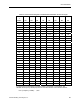
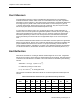
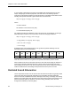


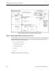
Table Of Contents
- About this Application Guide
- Chapter 1–Introduction
- Chapter 2–Physics of Sound
- Chapter 3–HVAC Sound Sources
- Chapter 4–HVAC Sound Attenuation
- Introduction to HVAC Sound Attenuation
- Plenums
- Duct Attenuation
- Duct Takeoffs and Divisions
- Duct Silencers
- End Reflection
- Environment Adjustment Factor
- Space Effect
- Radiated Sound Attenuation
- Chapter 5–HVAC System Sound Analysis
- Chapter 6–Minimizing HVAC Sound
- Appendix
- Glossary
- Index

Chapter 5–HVAC System Sound Analysis
Figure 16. HVAC System Layout for Sound Analysis Example.
Step 1. Actual Operating Conditions Increase
This calculation provides the sound pressure level increase for the fan at the actual operating
cfm and static pressure. Using the FLw formula, will yield the dB level increase that must be
added to each of the eight octave bands.
FLw = 10 Log Q + 20 Log P
= 10 Log 15,000 + 20 Log 3
= 10 (4.2) + 20 (0.477)
= 42 + 9.5
= 51.5
This value is in the second row of Table 26.
68 Siemens Building Technologies, Inc.