
Basic Documentation
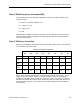
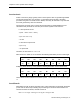
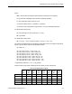
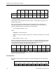
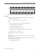
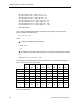
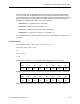
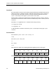
Table Of Contents
- About this Application Guide
- Chapter 1–Introduction
- Chapter 2–Physics of Sound
- Chapter 3–HVAC Sound Sources
- Chapter 4–HVAC Sound Attenuation
- Introduction to HVAC Sound Attenuation
- Plenums
- Duct Attenuation
- Duct Takeoffs and Divisions
- Duct Silencers
- End Reflection
- Environment Adjustment Factor
- Space Effect
- Radiated Sound Attenuation
- Chapter 5–HVAC System Sound Analysis
- Chapter 6–Minimizing HVAC Sound
- Appendix
- Glossary
- Index

Chapter 5–HVAC System Sound Analysis
Duct Section A
Airflow in the velocity range typically used in HVAC systems does not generate appreciable
sound within straight duct runs; therefore, no generated noise level (GNL) calculation
procedure was given in an earlier section. Rather, ducts may be assumed to only attenuate
the sound generated by other duct elements.
Following the procedure given on HVAC Sound Attenuation for Sheet Metal Ducts, first
calculate the P/A (Perimeter to Area ratio) for the HVAC system’s Duct Section A.
P = Duct perimeter in feet
= (36 in. + 48 in. +36 in. + 48 in.)
= (3 ft +4 ft +3 ft + 4 ft)
= 14 feet
A = Duct area in square feet
= (3 ft x 4 ft)
= 12 square feet
Therefore, the P/A ratio is 14 ÷ 12 = 1.16
With reference to Table 16, we can assume the following attenuation per foot of duct length:
63 125 250 500 1,000 2,000 4,000 8,000
Hz Hz Hz Hz Hz Hz Hz Hz
.165
dB
.111
dB
.074
dB
.049
dB
.033
dB
.022
dB
.015
dB
.010
dB
Multiplying these values by 14 feet yields the following attenuation in each octave band:
63 125 250 500 1,000 2,000 4,000 8,000
Hz Hz Hz Hz Hz Hz Hz Hz
2.3
dB
1.5
dB
1.0
dB
0.7
dB
0.5
dB
0.3
dB
0.2
dB
0.1
dB
These values are also entered into the HVAC system - sound analysis form shown in Figure
17.
Duct Elbow B
While airflow through an elbow generates sound, it also attenuates sound already generated
(in this case the fan sound). Following the procedure given for Elbow Airflow Noise in the
HVAC Sound Sources section, the basic formula is:
ELw = K + 10 Log F + 50 Log U + 10 Log S + 10 Log D + EC
70 Siemens Building Technologies, Inc.