
Basic Documentation
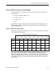
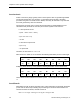
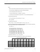
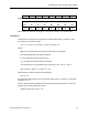
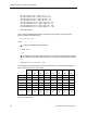
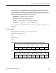
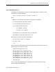
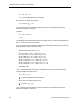
Table Of Contents
- About this Application Guide
- Chapter 1–Introduction
- Chapter 2–Physics of Sound
- Chapter 3–HVAC Sound Sources
- Chapter 4–HVAC Sound Attenuation
- Introduction to HVAC Sound Attenuation
- Plenums
- Duct Attenuation
- Duct Takeoffs and Divisions
- Duct Silencers
- End Reflection
- Environment Adjustment Factor
- Space Effect
- Radiated Sound Attenuation
- Chapter 5–HVAC System Sound Analysis
- Chapter 6–Minimizing HVAC Sound
- Appendix
- Glossary
- Index

Chapter 5–HVAC System Sound Analysis
63 125 250 500 1,000 2,000 4,000 8,000
Hz Hz Hz Hz Hz Hz Hz Hz
EC -95 -95 -95 -95 -95 -95 -95 -95
ELw 40 41 39 35 28 18 4 0
dB dB dB dB dB dB dB dB*
* Although this value adds up to -14 dB, a zero is entered as the net result since it is considered that a GNL
cannot be less than zero.
These values are now entered into the HVAC system - sound analysis form (Figure 17) as
Elbow B “GNL” entries.
Next, you must estimate the attenuation that the elbow will provide. To estimate the
attenuation provided by either a rectangular or round elbow, you must first calculate the
Frequency Width (FW) factor for the elbow at each octave band.
FW = (Frequency x Width) ÷ 1,000
Where:
Frequency = the octave band Hz.
Width = the nominal duct width in inches. (48 in. is used since the elbow is in the vertical
plane.)
FW = (Frequency x 48 in.) ÷ 1,000.
After the FW values are determined, refer to Figure 15 for the dB attenuation at each octave
band. (The rectangular, square, unlined with vanes curve applies.) The following chart lists
the calculated FW factors and the corresponding attenuation values from the
“RECTANGULAR, SQUARE, UNLINED, WITH VANES” curve.
63 125 250 500 1,000 2,000 4,000 8,000
Hz Hz Hz Hz Hz Hz Hz Hz
FW
3.0 6.0 12.0 24.0 48.0 96.0 192 384
ATTN:
3.1 dB 6.2 dB 7.1 dB 7.0 dB 6.9 dB 6.8 dB 6.8 dB 6.8 dB
These values are now entered into the HVAC system - sound analysis form (Figure 17) as
Elbow B “ATTENUATION” entries.
Duct Section C
Since this is the same size duct as Section A, the same attenuation per foot of duct length
applies:
63 125 250 500 1,000 2,000 4,000 8,000
Hz Hz Hz Hz Hz Hz Hz Hz
.165 .111 .074 .049 .033 .022 .015 .010
72 Siemens Building Technologies, Inc.