
Basic Documentation
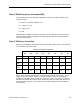
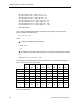
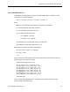
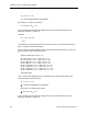
Table Of Contents
- About this Application Guide
- Chapter 1–Introduction
- Chapter 2–Physics of Sound
- Chapter 3–HVAC Sound Sources
- Chapter 4–HVAC Sound Attenuation
- Introduction to HVAC Sound Attenuation
- Plenums
- Duct Attenuation
- Duct Takeoffs and Divisions
- Duct Silencers
- End Reflection
- Environment Adjustment Factor
- Space Effect
- Radiated Sound Attenuation
- Chapter 5–HVAC System Sound Analysis
- Chapter 6–Minimizing HVAC Sound
- Appendix
- Glossary
- Index

Chapter 5–HVAC System Sound Analysis
St = 60 x 63 Hz x 2.3 ft. ÷ 1,250 = 7.0 K = - 27
St = 60 x 125 Hz x 2.3ft. ÷ 1,250 = 13.8, K = - 34
St = 60 x 250 Hz x 2.3ft. ÷ 1,250 = 27.6, K = - 42
St = 60 x 500 Hz x 2.3ft. ÷ 1,250 = 55.2, K = - 51
St = 60 x 1000 Hz x 2.3 ft. ÷ 1,250 = 110.4, K = - 60
St = 60 x 2000 Hz x 2.3 ft. ÷ 1,250 = 220.8, K = - 72
St = 60 x 4000 Hz x 2.3 ft. ÷ 1,250 = 441.6, K = - 90*
St = 60 x 8000 Hz x 2.3 ft. ÷ 1,250 = 883.2, K = - 150*
*Estimated Values
JC is a constant that depends upon the configuration of the junction and relates to the
junction’s ability to attenuate sound.
JC = -107 + Δr + ΔT
Where:
Δr = Junction Radius/Branch Duct Diameter
= 16 in. ÷ 16 in.
= 1.0.
ΔT = a turbulence factor that applies since there is another duct element (elbow B) within
five duct diameters upstream. However since M = 0.0, Table 10 indicates that ΔT will be
0.0.
Therefore, JC =-107 + 1.0 + 0.0 = -106
The following chart summarizes the terms and results of the JLw formula to determine the
GNL of this junction at each octave band.
63 125 250 500 1,000 2,000 4,000 8,000
Hz Hz Hz Hz Hz Hz Hz Hz
K -27 -34 -42 -51 -60 -72 -90 -150
10 Log F 18 21 24 27 30 33 36 39
50 log U 155 155 155 155 155 155 155 155
10 Log S 6 6 6 6 6 6 6 6
10 Log D 3.6 3.6 3.6 3.6 3.6 3.6 3.6 3.6
JC -106 -106 -106 -106 -106 -106 -106 -106
JLw 49.60 45.6 40.6 34.6 28.6 19.6 4.6 0
dB dB dB dB dB dB dB dB
These values are now entered into the HVAC system - sound analysis form (Figure 17) as
Junction D GNL entries.
74 Siemens Building Technologies, Inc.