
Basic Documentation
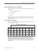
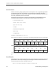
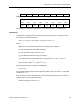
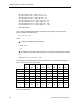
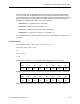
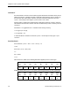
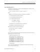
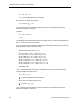
Table Of Contents
- About this Application Guide
- Chapter 1–Introduction
- Chapter 2–Physics of Sound
- Chapter 3–HVAC Sound Sources
- Chapter 4–HVAC Sound Attenuation
- Introduction to HVAC Sound Attenuation
- Plenums
- Duct Attenuation
- Duct Takeoffs and Divisions
- Duct Silencers
- End Reflection
- Environment Adjustment Factor
- Space Effect
- Radiated Sound Attenuation
- Chapter 5–HVAC System Sound Analysis
- Chapter 6–Minimizing HVAC Sound
- Appendix
- Glossary
- Index

Introduction to HVAC System Sound Analysis
Next, we need to come up with the attenuation that Junction D will provide. When a takeoff
occurs on a main duct, the available sound energy must divide between the resulting duct
runs after the takeoff. As a result, neither duct at the point where it leaves a junction can have
all of the sound power level energy that was available at that point. The following formula
estimates the resulting dB attenuation occurring at a junction:
Attenuation = 10 Log [Branch Area ÷ Total Area]
Branch Area = Branch Duct Area (square inch)
Total Area = Total Duct Area Leaving Junction (square inch)
Attenuation = 10 Log [8 sq ft ÷ 12 sq ft] = 10 Log [0.67] = 1.8
The 1.8 dB attenuation is entered into the HVAC system - sound analysis form (Figure 17) for
Junction D.
Duct Section E
Duct Perimeter = (32 in. + 36 in. + 32 in. + 36 in.) ÷ 12 = 11.33
Duct Area = (32 in. x 36 in.) ÷ 144
= 8
P/A = 11.33 ÷ 8
= 1.42
With reference to Table 16, the following attenuation applies per foot of duct length:
63 125 250 500 1,000 2,000 4,000 8,000
Hz Hz Hz Hz Hz Hz Hz Hz
.192
dB
.128
dB
.086
dB
.057
dB
.038
dB
.026
dB
.017
dB
.011
dB
Multiplying these values by the 16 feet yields the following attenuation in each octave band:
63 125 250 500 1,000 2,000 4,000 8,000
Hz Hz Hz Hz Hz Hz Hz Hz
3.1
dB
2.0
dB
1.4
dB
0.9
dB
0.6
dB
0.4
dB
0.3
dB
0.2
dB
These values are entered into the HVAC system - sound analysis form shown in Figure 17.
Siemens Building Technologies, Inc. 75