
Basic Documentation
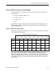
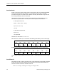
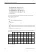
Table Of Contents
- About this Application Guide
- Chapter 1–Introduction
- Chapter 2–Physics of Sound
- Chapter 3–HVAC Sound Sources
- Chapter 4–HVAC Sound Attenuation
- Introduction to HVAC Sound Attenuation
- Plenums
- Duct Attenuation
- Duct Takeoffs and Divisions
- Duct Silencers
- End Reflection
- Environment Adjustment Factor
- Space Effect
- Radiated Sound Attenuation
- Chapter 5–HVAC System Sound Analysis
- Chapter 6–Minimizing HVAC Sound
- Appendix
- Glossary
- Index

Introduction to HVAC System Sound Analysis
Duct Takeoff/Junction H
Following the procedure given for Junction and Takeoff Airflow Noise in Chapter 3, HVAC
Sound Sources, the basic formula is:
JLw = K + 10 Log F + 50 Log U
B
+ 10 Log S + 10 Log D – JC
Where:
Elw = the net sound power level increase (or decrease if it is negative).
K = a factor dependent upon design conditions.
F = the octave band center frequency in Hz.
U
B
= the branch duct airflow velocity.
12 in. Diameter = 0.79 sq ft
1,200 cfm ÷ 0.79 = 1,528 fpm
S = the branch duct cross sectional area in 0.79 square feet
D for Takeoffs = Branch duct height in feet = 1.0 ft.
Determining the K values requires first calculating M.
M = UM ÷ U
B
(U
M
= 5,000 ÷ 4 = 1,250 fpm)
M = 1,250 ÷ 1,528
= 0.8
Next, the Strouhal number is determined for each octave band center frequency. Then the
graph in Figure 13 provides the K values.
Strouhal number (St) = 60 F D ÷ UB
St = 60 x 63 Hz x 1.0 ft ÷ 1,528 = 2.5, K = -21
St = 60 x 125 Hz x 1.0 ft ÷ 1,528 = 4.9, K = -28
St = 60 x 250 Hz x 1.0 ft ÷ 1,528 = 9.8, K = -35
St = 60 x 500 Hz x 1.0 ft ÷ 1,528 = 19.6, K = -44
St = 60x1000 Hz x 1.0 ft ÷ 1,528 = 39.3, K = -53
St = 60x2000 Hz x 1.0 ft ÷ 1,528 = 78.5, K = -63
St = 60x4000 Hz x 1.0 ft ÷ 1,528 = 157.1, K = -74
St =60 x 8000 Hz x 1.0 ft÷1,528=314.1, K = -95*
*Estimated Value
JC is a constant that depends upon the configuration of the junction and relates to the
junction’s ability to attenuate sound.
Siemens Building Technologies, Inc. 77