
Basic Documentation
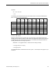
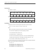
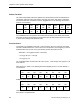
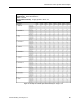
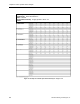
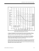
Table Of Contents
- About this Application Guide
- Chapter 1–Introduction
- Chapter 2–Physics of Sound
- Chapter 3–HVAC Sound Sources
- Chapter 4–HVAC Sound Attenuation
- Introduction to HVAC Sound Attenuation
- Plenums
- Duct Attenuation
- Duct Takeoffs and Divisions
- Duct Silencers
- End Reflection
- Environment Adjustment Factor
- Space Effect
- Radiated Sound Attenuation
- Chapter 5–HVAC System Sound Analysis
- Chapter 6–Minimizing HVAC Sound
- Appendix
- Glossary
- Index

Introduction to HVAC System Sound Analysis
Therefore:
JC = -107 + 0.0 + 0.0
= -107
The following chart summarizes the terms and results of the JLw formula to determine the
GNL of Junction H at each octave band.
63 125 250 500 1,000 2,000 4,000 8,000
Hz Hz Hz Hz Hz Hz Hz Hz
K -21 -28 -35 -44 -53 -63 -74 -95
10 Log F 18 21 24 27 30 33 36 39
50 Log U 159 159 159 159 159 159 159 159
10 Log S -1 -1 -1 -1 -1 -1 -1 -1
10 Log D 0 0 0 0 0 0 0 0
JC -107 -107 -107 -107 -107 -107 -107 -107
JLw 48.0 44.0 40.0 34.0 28.0 21.0 13.0 0
dB dB dB dB dB dB dB dB
These values are entered into the HVAC system - sound analysis form (Figure 17) as
Junction H GNL entries.
Whenever a takeoff occurs on a main duct, the sound energy is also divided between the
resulting duct runs after the takeoff, so that neither duct at the point where it leaves a junction
or takeoff has all of the sound power level energy. The following formula approximates the
resulting dB attenuation occurring at a junction:
Attenuation = 10 Log [Branch Duct ÷ Total Duct Area Leaving Junction]
= 10 Log [0.79 sq ft ÷ 3.9 sq ft]
= 10 Log [0.2] = 6.9
The 6.9 dB attenuation is entered into the HVAC system - sound analysis form (Figure 17) for
Junction H.
Siemens Building Technologies, Inc. 79